| SJ23 Tech Tip A08, (Updated 2024-10-31) Bobby Kawamura & Bob Schimmel | |||||||||||||||||||||||||||||||||
|
A Guide to Maintain Trailer Wiring and Lights. INDEX - Wire colour code, Light fixture, Wiring Diagram, Bargman Connector, Tools, Typical Faults. |
|||||||||||||||||||||||||||||||||
Part of the fun in sailing is to
explore new places. In order to explore new lakes with your SJ23 it is necessary to trailer the boat. North American road laws require a trailer
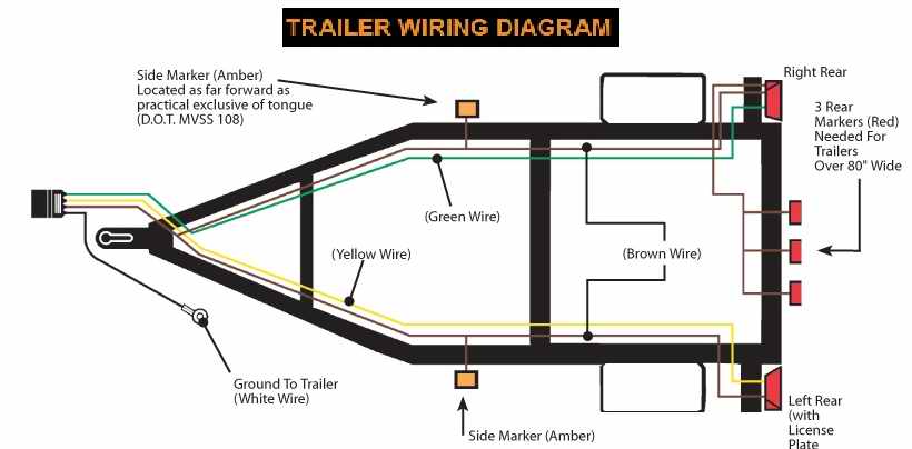
to be equipped with tail, stop, turn and clearance lights. An SJ23 trailer is wider than 80" and therefore requires the triple over width identification lights. Manufacturers build lights that meet these
regulations but it is the owner's responsibility to maintain them in operating
order. It does not matter the quality of your trailer and
lights, because whoever said, "the only thing you can count on is death and
taxes," never pulled a trailer. The third inevitable fate is, "trailer lights will quit". If you tow a trailer often enough you
will eventually have a problem with the lights. Often it starts with a small
irritant that takes a few minutes to repair. If you ignore those irritants, eventually they will
escalate and out of frustration you may replace the entire wiring harness with a new one.
In a 4 wire trailer wiring harness there are three separate circuits that distribute power; side and tail clearance lights, left turn signal light and right turn signal light. The brake lights for older North American vehicles consist of both signal lights switched on simultaneously. The standard wire color code for these three circuits is as follows:
The signal and brake lights are separate for European and Asian vehicles, adding one more circuit to the mix. North American vehicles have all but converted to separate signal and brake lights for improved safety.
The ground wire is used to complete the return path to the vehicle battery for all circuits. It is recommended to use a ground return wire instead of the metal frame of the trailer to ensure an uninterrupted electrical continuity back to the car battery. The colour code and the pin assignment for the trailer connector is usually printed on the box the connector is sold in. Some automotive supply houses may give it to you on a sheet of paper. Please follow the code. It makes resolving a problem so much easier. The electric brake wiring is purposely omitted from this diagram to minimize confusion. I'm not sure how withholding information eliminates confusion since electric brakes are crucially important for an SJ23 and must be wired correctly.
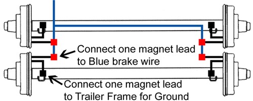
This electric brake wire connection is OK for a holiday trailer that never gets immersed in water. The white ground wires (shown as black) connected to the axle cannot conduct to the tow vehicle if the springs are installed with vinyl bearings over the mounting bolts. Don't use this technique on a boat trailer unless you enjoy crawling under the trailer to repair a brake wire connection.
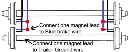
This electric brake wire connection is best for a boat trailer that gets immersed in water. Dual blue and white (shown as black) brake wires create redundancy and safety. On Panache the blue and white wires are connected together on a terminal strip tucked inside the side rail at the front of the trailer. Connect a single wire from each side to the trailer connector plug. Wiring repairs would be at the front that is seldom immersed. TOP
TOOLS and SUPPLIES - Maybe MacGyver can repair trailer lights with nothing but his wits and a Swiss army knife, but the rest of us mortals need the correct tools. A very useful tool is the circuit power test light which looks like a screwdriver but has a light bulb in the handle and has a wire with an alligator clip coming from the handle. It is priced around $5.00. Attempting to diagnose a trailer light problem without this tool is a tedious exercise in futility. To use the test light you connect the alligator clip to clean unpainted spot on the tow vehicle frame or ground wire (electrical ground). A bolt welded to the frame can provide a good solid ground. When the probe is poked into a wire with voltage the bulb will light up. This indicates the circuit has power. Another useful tool is a continuity checker. This tool is used to see if a wire has continuity (an unbroken path) or there is no resistance to ground. The continuity checker often looks like a pen flashlight. It has an alligator clip and a probe. The difference is the continuity checker's battery will light the bulb without external power from the tow vehicle. It is wise to switch all vehicle power off before using a continuity checker. Not all of these tools are necessary for every problem, but they are all useful for a problem you may encounter. TOP
|
|||||||||||||||||||||||||||||||||
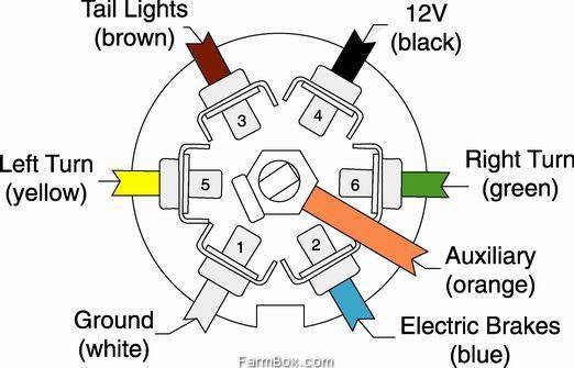
| BARGMAN 7 PIN
TRAILER CONNECTOR - The majority of vehicles use this style connector, especially if you
have electric brakes. 7 conductor stranded cable, matching the standard colours shown below, is available from automotive parts stores. It comes with a heavy duty insulation and will last a zillion years. Sometimes the Bargman connector is already attached. The 12V power on pin 4 can be used to maintain the charge of the breakaway battery. To minimize confusion, use the same conductor colours as shown below.
|
|||||||||||||||||||||||||||||||||
|
|||||||||||||||||||||||||||||||||
| TYPICAL FAULTS - Why don't the lights work? They did the last time the boat was towed! No
one ever damaged the wires, they should work! But things do happen to trailer
wires. Failure to disconnect the wiring plug while disconnecting the trailer will
rip the connectors apart. A brittle sun baked plastic tie wrap will leave wires
dragging on the road to grind off the insulation. Aged insulation can expose the copper wire causing a
short when it touches a ground. Salt water corrosion will attack all exposed copper in the connector, unsealed wire and light bulb sockets. Vibration can cause failure of ground wire nuts. Trash on the road can be
kicked up breaking tail light lenses. Large dips in the launch ramp
can smash tail light housings. Rats find wire insulation tasty. There are
numerous reasons for failure and none of them are anybody's fault. Well........!
There are several things that can and will go wrong with the trailer lighting circuit. They can be grouped into classes so they may be systematically checked and eliminated. Problems include:
AN OUNCE OF PREVENTION
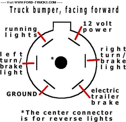
HOW TO FIND AND CORRECT A FAULT - There are different approaches to solving a trailer light problem. The best approach depends on your situation and temperament. The first technique is to apply common sense. If you know everything was working a few minutes ago and the left turn signal quit working it might be a good idea to test the bulb first. Beware when using the common sense technique, some of your assumptions may be wrong. When intuition fails to solve the problem, a more rigorous approach may be necessary. Difficult problems require systematically testing all circuits for proper operation. Preparation can help in finding problems. It is more difficult to find the problem when you do not know what to expect. In the driveway at dusk when you have all the tools handy, perform some of the diagnostic tests to see if your vehicle is wired properly. You can inspect your trailer to see if the insulation is holding up. Check to see if the light bulbs have not burned out. How do you determine if the problem is with the vehicle or the trailer? Easy first check the car then check the trailer. TOPCHECK THE TOW VEHICLE - First and foremost check the vehicle for proper operation. With the trailer disconnected turn on the clearance lights at the headlight switch, and then switch them off. Have an assistant use the right and left turn signals then brakes while you observe their operation standing in back of the vehicle. If everything functions normally on the vehicle then check the trailer plug on the vehicle. A typical tow vehicle plug is an in-line four-pin plug. It has three female pins and one male pin. The female pins carry the voltages for the different lights; the male pin is the ground or return for all the circuits. Visually inspect the white wire to see if it connects to ground. Verify ground connectivity by connecting the continuity checker between the trailer ball and the white wire of the plug. If the continuity checker lights, then ground is OK. Remember white leads connect to ground. Check all connectors before beginning any process. There is a Trailer Lights Tester you can buy from an automotive parts store.
It
measures a trailer jack to determine if it is wired and working correctly. Instead of trailer lights it has three
LEDs. The LEDs are labelled to match correctly wired trailer lights.
The
first LED is labelled TL for tail lights (clearance). The second is labelled RT for right
turn signal. The last is labelled LT for left turn signal. I lieu of a plug-in tester, a circuit power tester (light bulb with alligator clips) or multimeter can be used. To use either, clip one lead to frame ground of the vehicle; a clean unpainted spot. Switch the vehicle clearance lights on. Poke the probe into the tail light (brown) wire terminal. The power tester should light up. Probe the yellow and green wires, they should remain dark. Turn off the clearance lights. Flip on the left turn signal. Probe the Yellow wire, the tester should blink. Probe the green and brown wires, they must show dark. Change to right turn signal. Probe green wire, the tester should blink. Probe yellow and brown wires, they must show dark. Turn off the turn signal. Have an assistant press the brake pedal. Probe green and yellow wires, the tester should light up. Probe brown it must show dark. If any of the lights fail to light when supposed to, then there is probably a faulty connection of the plug to the vehicles wiring. Follow the wire from the plug to the crimp joining it to the factory wiring. Wiggle the crimp and re-check the circuit. If it fails again then re-crimp the junction and check the circuit. If it still fails use the circuit power tester to check the vehicle wiring on the vehicle side of the junction. If any of the wires have power when they are not supposed to then it is probably wired to an incorrect wire on the vehicle. A voltmeter can be substituted for the power circuit tester. Instead of lighting it will read a voltage around 12 volts. Below is a table of light functions to check with the test light. Activate the function on the left side of the table then use the circuit tester to probe for the light at the three terminals on the connector.
If your vehicle is a fairly late model and popular for towing there are Y adapters that connect to the wiring harness using standard OEM connectors. They are about $40.00 and will save you a lot of time. The quality of the connector is high and relieves the installer from having to crawl under the car poking into wires. Some Y adapters have built in diagnostic LEDs. That being said, adapters do not help if there is a malfunction in the system or you are one of the unlucky people who do not have a popular automobile. Some vehicles have separate brake and turn signal circuits. The majority of import and some domestic vehicles are wired in this configuration and is becoming more popular with domestic vehicles. If your vehicle has this configuration and your trailer has only four lights (filaments), then you can install the extra lights or a converter box to reduce it to a four wire system. The converter box costs about $12.00 US. Basically the converter consists of some diodes to steer the current to the appropriate trailer filament while keeping the current away from the vehicle signalling lights to prevent erroneous light pattern. Alternatively you could install a 7 pin trailer connector and the extra lights and wiring to create the same lights on the trailer. The cost difference is not that great and you have the advantage of an extra light on the trailer. TOP CHECK THE TRAILER - Visually inspect the wires as they run along the frame, looking for cuts in the insulation. Look carefully at places where wires are attached to the frame. Look at the general condition of the wires. Is the plastic insulation dry and brittle? Inspect the trailer plug, it has three male pins and one female pin. Problems with trailer wiring can blow fuses on the tow vehicle. Have some extra fuses, in the rating of your vehicle's tail light turn signal and brake lights, handy. Check trailer ground. Do not rely on the hitch ball to provide a good ground. Visually inspect the white wire look for a frame attachment. If you have a late model automobile you might want to purchase an inline circuit breaker before plugging in any trailer. This could prevent costly damage to the automobile's computer. The inline circuit breaker is about $14.00. Some have color coded LEDs to indicate if the circuit is good or bad. Wiring color code on a trailer can only be trusted for a couple of feet, that is the length of the plug's pigtail. From that point on the wire may change to whatever color wire the installer used. Physically follow the wire instead of depending a wire color. Inspecting for an open circuit in the trailer is easy. Clip the alligator clip of the continuity checker to the trailer frame. One at a time, poke the continuity checker's probe in the plug terminals. Each should light up. If white fails to light then check the ground wire. Failure of brown wire to light indicates a tail light problem. Yellow or green failing indicates a turn signal circuit is open. If any circuit fails to light the checker then the circuit has a failed connector, ground or burned out bulb. If you have spare fuses then plug in the trailer. Turn on the tail lights. Use the left turn signal. Use the right turn signal. Depress the brake pedal. If there is any problem unplug the trailer. To check the trailer's ground and three circuits for shorts, remove all light covers and light bulbs on the trailer. Remember the side marker lights. They are easy to overlook. If any bulbs are in place they will invalidate the test by giving a false indication of a short circuit. Use continuity checker to test the ground. Clip the alligator clip to the trailer frame; poke the continuity checker's probe in the plug to the white wire. The continuity checker should light. If it does not then the ground wire is bad. If this is the case then none of the lights should have worked when the trailer was connected to the vehicle. After a good ground has been established, the tail light and signal circuits can be tested for a short. Probe the other wires in the trailer's plug, none should light. If any of the plugs wires have a short, then in that circuit is connected to ground. If the vehicle blows a fuse in the absence of a short circuit, there might be a circuit-overloading problem. The load is most likely on the tail light circuit. To calculate the load you will have to make a wire diagram for the trailer. An ammeter can measure it directly.
1/Rtot = 1/R1+1/R2+1/R3+1/R4+1/R5+1/R6+1/R7 The resistance of a light bulb is much lower at low temperature. The resistance of a cold tungsten filament is about ten times lower than one at normal operating temperature. From the manufacturer's spec sheet, the resistance of the model BP1156 stop light bulb is 5.53 ohms. You must be careful, the resistance is rated for a load. Measuring the same light bulb with a multi-meter shows 0.5 ohms without a load. Use the light bulb rating listed by the manufacturer in your calculation. For our example of six bulbs in parallel, having a resistance of 5.53 ohms each, the total resistance is 0.79 ohms. Using the formula V=IR ,12=I*0.79, gives a total current draw of 15 amps. A vehicle with two tail lights and four side marker lights has a total of six lights. If these are wired in parallel, the total current draw for both systems is 25 amps. The fuse in a Toyota Land Cruiser for the tail light circuit is rated at 15 amps. Attaching a trailer with six clearance lights will blow a fuse, as the circuit would have to handle 30 amps to handle the extra load. A solution to this problem is to install a relay. These calculations have neglected resistance in the wires. Bigger wires (Lower Gauge) have less internal resistance. If the gauge of the trailer wire is too small for the current it is carrying, it will burn. The wires in the tow vehicle must be large enough to carry the combined current of the vehicle and the trailer.
At right is a table of wire sizes and their current carrying capacity at lengths under 100ft. Be sure the amperage rating of the fuse is low enough to blow before exceeding the current rating as shown in the chart at right. A fuse with a current rating equal or lower than the wire will protect the wire from melting. TOP
TEMPORARY LIGHTS FOR A BOAT TRAILER - A major problem with boat trailer lights is that salt water and electrical systems do not mix very well. One solution is to keep the lights dry. To do this you may wish to build a towing light bar. One can be made inexpensively from a (2x4)" and some trailer lights. Depending on how much electrical "junk" you have lying around, it can be made for as little as $10.00. To construct the light bar, cut a six-foot length of (2x4)" and bolt the light fixtures to the board. Wire the lights just like a conventional trailer except that you need a ground wire for a return path. One advantage of this system is that is that the light bar can be built and tested in the convenience of the garage. It is better to work fifty feet away from a refrigerator full of beer, than on the gravel of a RV storage yard. It eliminates the problem of hooking up a small fortune of poorly maintained trailer lights to your new Range Rover. If you have a light bar then you know it will work correctly. Or at least you know how it should work. To use the light bar simply tie the bar to the back on the boat trailer. Then push the plug into the jack on the tow vehicle. The wire harness should be tied to the trailer so it does not drag on the ground. The bar can be connected to any boat or trailer in a matter of minutes. If nautical aesthetics are desired a brass cleat can be used to tie the rope. TOP TIP & HINTS
SUMMARY - I hope this guide helps you to understand and solve your trailer wiring problems. It will not prevent problems but it will help to repair them. You might as well learn how to fix them, because trailer lights always go bad, eventually, usually just when you need them. It pays to be prepared. Understanding the principals of fault correction, knowing the schematic and having the proper tools are necessary steps in being prepared. Fair sailing, fair towing. Bobby Kawamura TOP The trouble with fixing trailer lights the first
time is that few people appreciate how difficult it was! |
|||||||||||||||||||||||||||||||||
A
Bit of Trailer Light Humour.
|
|||||||||||||||||||||||||||||||||
|
Return to Tech Tip Index. . . . . . . . . . . . . . . Have a Question? |
|||||||||||||||||||||||||||||||||
 In the diagram
at right the light bulbs are represented by resistors R1 to R7. The diagram re-drawn becomes a parallel circuit and is somewhat easier
to understand. In this case the current supplied by the battery splits up,
and the amount going through each resistor depends on the resistance of each
bulb. A little algebra is necessary to find the total load. The total
resistance of a set of bulbs in parallel is found by adding up the
reciprocals of the resistance values, and then taking the reciprocal of the
total.
In the diagram
at right the light bulbs are represented by resistors R1 to R7. The diagram re-drawn becomes a parallel circuit and is somewhat easier
to understand. In this case the current supplied by the battery splits up,
and the amount going through each resistor depends on the resistance of each
bulb. A little algebra is necessary to find the total load. The total
resistance of a set of bulbs in parallel is found by adding up the
reciprocals of the resistance values, and then taking the reciprocal of the
total.