| SJ23 Tech Tip E04a, (Updated 2015-03-23) Bob Schimmel | ||||||||||||||||||||||||||||||||||||||||||||||||||||||||||||||||||||||||
|
Back to Pulse Charge & Measure Battery State - Desulphate Plates. |
||||||||||||||||||||||||||||||||||||||||||||||||||||||||||||||||||||||||
|
There are many web sites related to pulse battery chargers. Some years ago the author of Home Power Systems provided the following schematic and parts list. I have not built this charger but was intrigued by its simplicity. Reading the operation section will give you some insight to how a pulse charger works. It may not be worth your effort to build this circuit considering that ready made products are likely cheaper and will take a lot less of your time. It may also be difficult to source the discrete components today, You be the judge. SOME THEORY - The following is a brief operational description to maintain a liquid filled lead-acid deep cycle battery as could used on an SJ23. The usual practice in maintaining a battery is to periodically apply an equalizing charge. If done long enough, it ultimately cleans the battery plates but with lots of charge current applied. On a sailboat, where you don't have shore power for a charger, you generally don't run your engine generator long enough to have the desired effect and most sailors are more interested in sailing than battery maintenance. This explains why so many sailors are shocked when the engine can't start. A deep cycle battery can be desulphated with pulse charging using very little power. Use of the pulse circuit shown below will eliminate the need for equalize charging plus restore and maintain the battery to "like new" condition. This device is especially useful for automotive or marine batteries that sit unused for a long time. What follows is simplistic description of the pulse charging. A battery possesses a resonant frequency, depending on it's physical properties, which is approximately 2 to 6 mHz. By physically shocking the battery plates with pulses of electricity, similar to ringing a bell, the sulphate crystals are broken free to expose more of the plate surface. Eventually all the surface is exposed to the electrolyte, restoring the storage capacity to "like new." The free sulphate crystals return to solution.
NOTES
INSTALLATION CONSIDERATIONS - There two ways you can connect a desulfator to a battery. Across the battery so the desulfator draws input power from battery and then discharges into the battery. The other method is to take input power from a solar panel and then discharge into the battery. The second technique is more efficient because when the sun goes down, the charge current stops and the energy is retained in the battery. The output of the desulfator can be left connected to a battery continuously. Think of it as a technique for occasionally charging a battery when the sun shines. Be aware that there are battery desulfators available that draw power from commercial AC. They work very well but its just a bit difficult to move your boat around unless you have a very long extension cord! The pulse charger should be installed in a convenient location that is electrically close to the battery to minimize signal loss for the high voltage charge pulses. Connect the pulse charger 12 VDC output leads directly across the battery terminals. Connect the pulse charger input leads to the solar panel. Connect all other electrical leads to the battery; outboard generator, DC distribution panel, observing the correct polarity. If you hear electrical "noise" on the VHF radio then some of the pulse energy is leaking through the radio and likely into the boat's electrical system. To block the RF, install some ferrite beads on the + DC cables (generator, radio, distribution panel input) as electrically close as possible to the battery. The beads may have to be taped to the cable if a specific spot along the cable attenuates the RF signal the most. You can get a ready source of ferrite beads from your local electronics recycler. They will likely have a box full of computer cables. Look for the cables with 1" long "bump" (ferrite bead) near one connector. Chop off the cable at both ends of the bump, remove the heat shrink, and push the cable out from inside the bead. Now slide the bead over the power line. To be really effective, loop the power cable several times through the bead. The ferrite should attenuate lots of RF. Sometimes several beads are required to do the job. For absolute control you should install a switch for each power input line (solar panel, engine generator, wind generator, etc.) to isolate any one of them in the event of a trouble. Install and label the switches on the power control panel. All too often you see only the load switches labeled and very seldom are power input switches wired or labeled. To minimize the possibility of confusion out on the water, the power input switches should be marked or shaped different than the load switches. NOTE -
I offer this information for those who want to
experiment.
I found it
is easier to buy a Morning Star SunGuard SG-4 solar controller as I have
other things to do and there is only so much time left in my life. Bob Schimmel
TOP |
||||||||||||||||||||||||||||||||||||||||||||||||||||||||||||||||||||||||
|
Return to Tech Tip Index. . . . . . . . . . . . . . . Have a Question? |
||||||||||||||||||||||||||||||||||||||||||||||||||||||||||||||||||||||||
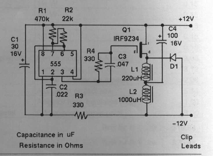 SCHEMATIC DIAGRAM and OPERATION -
The schematic shown at right is essentially a switching DC-to-DC
converter, taking 12 VDC power
from a battery and pulsing it out as a voltage spike back into the battery.
This is very similar to a capacitive discharge ignition (CDI) system
used in a gas engine during the early 1970s. In this circuit the pulse rate is
set by the 555 timer chip, U1 (distributor shaft) that switch the MOSFET
Q1 (ignition points operated by distributor shaft) at a 1 kHz rate. When Q1
is in the non-conducting state, current is drawn from the battery through
L2 (ignition coil primary winding) so it charges capacitor C4 (capacitor
wired across the points) slowly. Q1 is then switched on for 50
microseconds, causing C4 to discharge through L1. When Q1 is switched off
again, the stored inductive energy in L1 pulses back into the battery
through diode D1. This pulse of current can be as high as 6 amps with a
peak voltage of 50 VDC lasting for only milliseconds. The peak voltage will
decrease as the battery's internal resistance declines (battery approaching
full charge) or it's function is
restored to normal. The use
of an inductor L1 to create this high voltage pulse is what makes it possible to restore a
badly sulphated battery with a high internal resistance.
SCHEMATIC DIAGRAM and OPERATION -
The schematic shown at right is essentially a switching DC-to-DC
converter, taking 12 VDC power
from a battery and pulsing it out as a voltage spike back into the battery.
This is very similar to a capacitive discharge ignition (CDI) system
used in a gas engine during the early 1970s. In this circuit the pulse rate is
set by the 555 timer chip, U1 (distributor shaft) that switch the MOSFET
Q1 (ignition points operated by distributor shaft) at a 1 kHz rate. When Q1
is in the non-conducting state, current is drawn from the battery through
L2 (ignition coil primary winding) so it charges capacitor C4 (capacitor
wired across the points) slowly. Q1 is then switched on for 50
microseconds, causing C4 to discharge through L1. When Q1 is switched off
again, the stored inductive energy in L1 pulses back into the battery
through diode D1. This pulse of current can be as high as 6 amps with a
peak voltage of 50 VDC lasting for only milliseconds. The peak voltage will
decrease as the battery's internal resistance declines (battery approaching
full charge) or it's function is
restored to normal. The use
of an inductor L1 to create this high voltage pulse is what makes it possible to restore a
badly sulphated battery with a high internal resistance.