| SJ23 Tech Tip F01, (Updated 2025-02-21) Bob Schimmel, Quinton Tormanen. | |||||||||||||||||
|
Mechanical Boom Vang with Internal Gas Spring. |
|||||||||||||||||
|
I made this variable length mechanical boom vang
for Panache to keep the boom above my head and to be the extra pair of
hands when reefing or lowering the mainsail. There is enough
force from the internal "gas spring" to offset the weight of the boom
so the mainsail can assume its designed shape in light
air and the leech doesn't cup or stretch prematurely when the boom is
sheeted in. However, if I use my mainsheet to its
In summary, a variable length vang allows you to set a perfect leech shape to match the jib, induce twist in the mainsail to spill wind or to support the boom during reefing, at any angle the boom is sheeted. But the real advantage is what it does for the shape of a full mainsail in light air. It pulls very well with the correct draft. This has to be experienced to be appreciated. NOTE 1: Before you consider adding a mechanical vang to your inventory, take the time to think through all the mainsail controls on your boat. If you usually adjust the height of the gooseneck to control mainsail shape then a rigid boom vang cannot work for you. A mechanical vang requires the gooseneck to be fixed to the mast. If you can accept operating an SJ23 with the gooseneck fixed to the mast, then you can consider a mechanical vang.
NOTE 2: It is advantageous to extend the vang control line to the cockpit from where you can see the curve of the leech as you adjust the vang tension. No more guessing the mainsail shape after crawling off the cabin top to adjust it. This saves a lot of time when things get dicey out there.
NOTE 3: Also read Tech Tip F08, Boom Jibe Preventer, as there are many useful benefits to be had with a preventer. |
|||||||||||||||||
|
1 - DESIGN CRITERIA of a VARIABLE LENGTH PNEUMATIC VANG. |
|||||||||||||||||
 MATERIALS - All
components are made of aluminum. The gooseneck was a critical and
difficult component to fabricate from stock aluminum but the tubes were relatively easy
to prepare. The end fittings for the tubes were machined
from solid aluminum stock using a metal lathe
to achieve a precision fit and then glued with silicon sealant and
fastened with screws for strength. You can make a variable length
vang as shown here or a fixed length vang (described
below) for simplicity. MATERIALS - All
components are made of aluminum. The gooseneck was a critical and
difficult component to fabricate from stock aluminum but the tubes were relatively easy
to prepare. The end fittings for the tubes were machined
from solid aluminum stock using a metal lathe
to achieve a precision fit and then glued with silicon sealant and
fastened with screws for strength. You can make a variable length
vang as shown here or a fixed length vang (described
below) for simplicity.
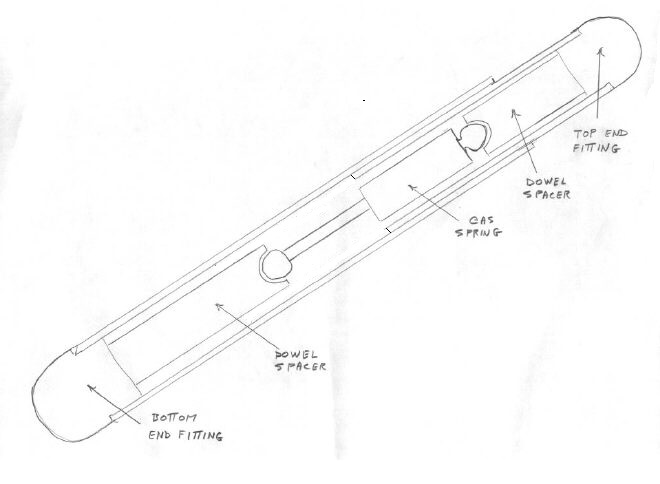
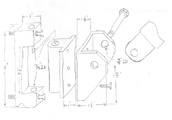
This is a pencil sketch of my design with the vang shown right side up, installed about 300 up from horizontal. The bottom fitting is connected to the vang gooseneck on the mast. The top fitting is connecting to a track under the boom. The gas spring rests between two dowels to create maximum stroke. A WORD OF CAUTION - A pneumatic vang equipped with an 80lb. gas spring can exert a surprising amount of force on the mast and boom. If the gooseneck were to break while you are sailing, it could damage the deck. So machine all the fittings to the closest possible tolerance and don't scrimp by using underrated components or undersized material. Also, keep the gooseneck bearings lubricated with a light water proof grease.
HINT - If you have fixed the height of your boom vang for your mechanical vang and want to install a mast gate as shown in Tech Tip F07, then position the gate so the bottom mainsail slug DOESN'T rest in the gate with the sail hoisted. The gate is weaker than the kerf of the mast and you don't want it to collapse under load while sailing.
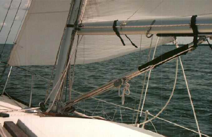
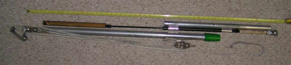
FROM THE SJ23 MANUAL - "The length of the mast extrusion is not limited. However, two 1/2" wide black bands (use electrical tape) are to be maintained on the mast. The lower edge of the upper band is to be no higher than 26’ above the mast step. The upper edge of the lower band must be maintained at 2' above the mast step. The mainsail, when hoisted, shall not extend its topmost portion above the lower edge of the upper band and shall not be down hauled below the upper edge of the lower band." I hope this is clear as I paraphrased it from the manual. The bottom line is that if you sail your boat within these constraints, you may as well fix your gooseneck to the mast. VANG LENGTH - Proportion the length of the vang to fit the mounting locations on your boat. The length overall of the vang for an SJ23 (bottom mounting bolt to top mounting bolt) is 44" compressed and 47" extended. The compressed length is set by the length of the internal dowels and the gas spring, fully compressed. The extended length is set by the control line outside tubes. In working mode the vang is ~46" long. The vang is rests at ~300 up from the deck. When the vang is extended, the boom is raised just enough to open up the leech. Regardless of how much measuring you do, the adjustable fitting on the track under the boom will absorb and correct your last mistake! Always build your design with some margin to compensate for error. You will find an optimum position under the boom. PARTS - Shown below is my vang during reconstruction to receive a new 27" long gas spring. The parts are laid out in order of assembly. The top fitting was removed from the aluminum tube and is laying on the right, at the end of the dowel. This is a new gas spring with 85 pounds air pressure and enough stroke for the required operating range. There were many times when I wanted to lift the boom higher so the extra stroke will provide that. The extra stroke also allows me to pull the boom in closer with less fear of bending or breaking it on the fully compressed vang. In the photo below the components are laid out with the gas tube at the top of the vang so the oil flows down to the seal, thereby maintaining the seal for longer life. This also makes it easy to assemble. Below are the component dimensions:
Note the aluminum tape wrapped around the black barrel of the gas tube. The tape increases the diameter so it fits snug inside the inner tube. This tape does not slide so it doesn't wear out. It is also at the top of the assembly so it stays dry. I drilled a drain hole at the bottom of the lower tube because I found water inside. This spring has 80 pounds of push (pressed into a bathroom scale), which is quite a bit more than my original gas spring. While the control line will have to be pulled in all the time to adjust the height of the boom, the 80 pounds push is enough to dispense with the topping lift while reefing. TUBES - The aluminum tubes are 1/8" thick wall. Use tubes that are at least 1/8" thick to create a solid support for the end fittings. If you want to use thinner tubing, then increase the diameter to prevent buckling. The outer tube is 1 5/16" OD and the inner tube fits snug inside, telescopic style. Aluminum tubing is manufactured in concentric dimensions so adjacent sizes fit, almost machine like. Strive for a reasonable overlap so the tubes stay in column to minimize jamming and wear. The bottom tube is the outer one at 37" length and the upper tube is the inner one at 22" length. GAS SPRING & POSITIONING SPACERS - Use an automotive gas spring (type used to lift a hatchback, etc) inside the inner tube, (see drawing above) to create enough push (~70 lbs.) to offset the weight of the boom with the mainsail folded on it. If you find a spring that has more push don't worry, you have to compress the vang with an external control line anyway. Use a gas spring with round end fittings so it centers on the dowel spacers and therefore never touches the inside of the tubes. If the OD of the gas spring barrel is smaller than the ID of the inner tube, wrap tape around the barrel to center it in the tube. I used several wraps of aluminum furnace duct tape. Install the spring with the pressurized black barrel at the top so the oil inside the barrel flows down to the seal to keep it lubricated and retain the gas pressure.
Update FOOD FOR THOUGHT - I received my monthly news letter from RockAuto and it has an interesting article about replacement gas spring liftgate to support a hatch, trunk, hood, etc. This is when I learned that some are electrically powered with an internal motor and a long threaded rod. This could be an interesting way to operate a boom vang and eliminate a line across the deck, provided you have the power to drive it. Just extend the power cord to a 3 way spring loaded toggle switch to raise (extend) or lower (compress) the vang. I suggest installing the switch in the cabin where you can reach it by standing in the cockpit so you can see the sail shape as the boom is being raised or lowered. Given how heavy some hatches are, this lift support would have sufficient power to lift a boom. TUBE END FITTINGS - Use a metal lathe to machine the end fittings so they fit snug inside their respective tube. Glue (marine adhesive) and bolt them in place. The fittings are under some tension but mostly compression loads as they operate. Make sure they can swing freely, without binding, for the full travel of their function; 900 arc for the bottom joint and 1800 for the top joint. The slightest amount of binding or limited movement will cause metal fatigue and possible failure. NOTE: There are many different styles of joints and end fittings you can make. Someone gave me the fittings and I adapted the tubes to them with a machine lathe and a vertical milling tool. I have a tendency to make things ready for WWWIII. If you think this is too complicated, pick another design that is within your tooling capabilities. Just make sure it CANNOT come apart.
|
|||||||||||||||||
|
2 - DESIGN CRITERIA of a FIXED LENGTH VANG |
|||||||||||||||||
|
TUBES - The inner and outer tubes should be made from thick wall aluminum (about 1" OD) that fit snug inside each other (telescopic). Strive for maximum overlap to minimize jamming and wear. Observe all the points noted above in GOOSENECK, KEEPING THE TUBES SLIDING and ADJUSTING THE VANG.
DETERMINE THE LENGTH - This is a simple
matter of drilling a sequence of 1/4" holes, about 1" apart, and inserting
a pin through one of them. If the pin goes through both tubes,
the vang length is fixed. Some sailors prefer this for simplicity.
If the pin is inserted
through the inner tube the vang can be
extended up
from the bottom stopper pin. The outer tube will rest on the pin.
Tie the pin to the tube so you don't loose it. |
|||||||||||||||||
|
INSTALLATION |
|||||||||||||||||
|
Regardless of which vang you make, the installation procedure on the boat is the same.
SAFETY NOTE: Lock
the vang control line when in the compressed position and keep your face away from
the end of the tubes. A gas spring in good condition can exert
enough force to knock your teeth out! |
|||||||||||||||||
|
ADJUST THE VANG -
Install a light 3:1 block and tackle around the vang to pull
the boom down; thereby controlling mainsail twist. This is sufficient
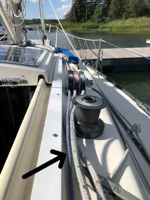
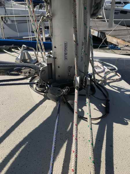
mechanical advantage to overcome the CONTROL LINE TO COCKPIT - In 2022 I installed a longer control line (5/16") to extend it to a cockpit rope clutch on the starboard cabin top. This is easier to operate than reaching over the cabin. Because I'm standing in the cockpit, I can look up along the leech, which is a perfect view of the telltales. The 85 pound gas spring lifts the boom and the vang line works in opposition to lower it. So all I have to do is release or pull the line to adjust the twist. Voila, the entire mainsail, top to bottom, now pulls. However, cockpit control is only possible if the turning block under the vang is installed inline with the turning axis. See Tech Tip F05. This ensures uniform line tension and vang length when the boom swings through its full arc. The diagram above depicts the external control line on the under side of the vang, looking up from the deck. It illustrates how the blocks are mounted and where the line goes. The inner (top) tube connects to the boom. With the combination of the gas spring and the control line in the cockpit, I can readily adjust the vang to have all telltales flying or the top ones stalled to reduce heel.
KEEP THE TUBES SLIPPERY -
After a few years of use, the two aluminum tubes sliding against each
other will wear which is evidenced by the black metal dust left on
the surface. The aluminum oxide dust washes off fairly easy with a household
cleaner and a rag, but don't touch it or let it contact your just cleaned
mainsail. This stuff can stain with a tenacity similar to high
quality printing ink. It DOES NOT come off.
(Like a lot of things, prevention is better than a cure).
The solution to this problem is to apply a light coat of lithium or
synthetic grease
between the tubes to minimize friction. (Lithium & synthetic grease resist washing out with water). To keep
the grease clean (minimize abrasion)
and to keep the sails off the vang, you SHOULD add a dust cover over the
junction of the two tubes. I use a black nylon sleeve, slipped over
the top end of the outer tube and tied with a light line around the inner
tube. The sleeve hangs down, overlapping the outer tube. This
sleeve is very effective to keep the mainsail off as it flakes over the
boom. My SJ28 buddy uses an automotive rubber boot (bellows) from a
rack & pinion steering system to protect the grease. That's natural, he's a gear head. Both the top
and bottom ends are fastened to the tubes to create a water tight seal.
These boots are made of a rubber like material that resists oil so they
should last. They're available from UAP or NAPA for less than $10.00
Can. He also assures me that anodizing the aluminum tubes does not
eliminate the wear between them but it sure makes them look good.
Lubricate all other fitting with grease so they move freely. |
|||||||||||||||||
|
CONCLUSION |
|||||||||||||||||
|
While I've been quite specific on the quality of the material and the
tolerances required in the making of this vang, you can thank yourself for
your meticulous workmanship the first time you have to reef in stormy
weather. I've adapted to this "toy" so easily that I've forgotten what
it was like to sail without it. In short, it's a real godsend when
sailing solo. Since I've posted this tip, I know of several people who've
made a vang using this design and all report the same experience. It
may be a lot of work to make, but the rewards come with use and you'll be
impressed with the performance. |
|||||||||||||||||
|
Return to Tech Tip Index. . . . . . . . . . . . . . . Have a Question? |
|||||||||||||||||
 full 8:1
mechanical advantage, there is a risk of bending the boom over the end
of the fully
compressed vang. So I am very careful with how hard I pull in the main sheet.
full 8:1
mechanical advantage, there is a risk of bending the boom over the end
of the fully
compressed vang. So I am very careful with how hard I pull in the main sheet. 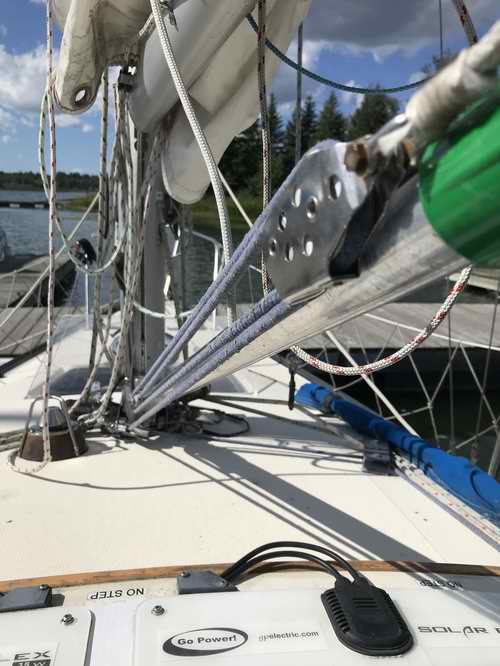
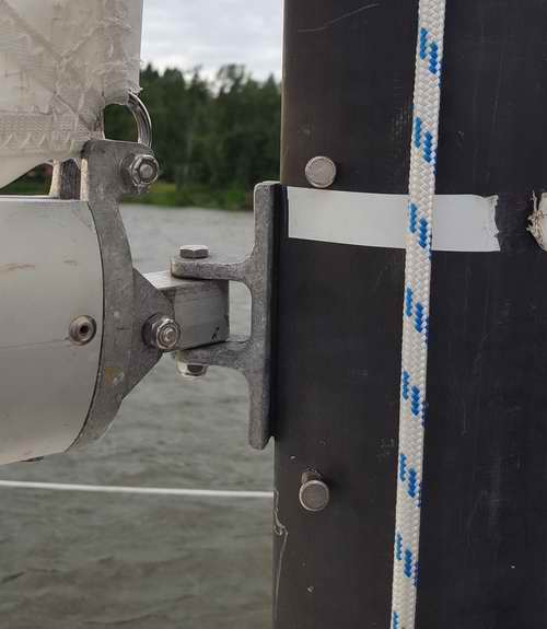
 FIXED GOOSENECK - The position of the
boom gooseneck must be fixed
FIXED GOOSENECK - The position of the
boom gooseneck must be fixed 
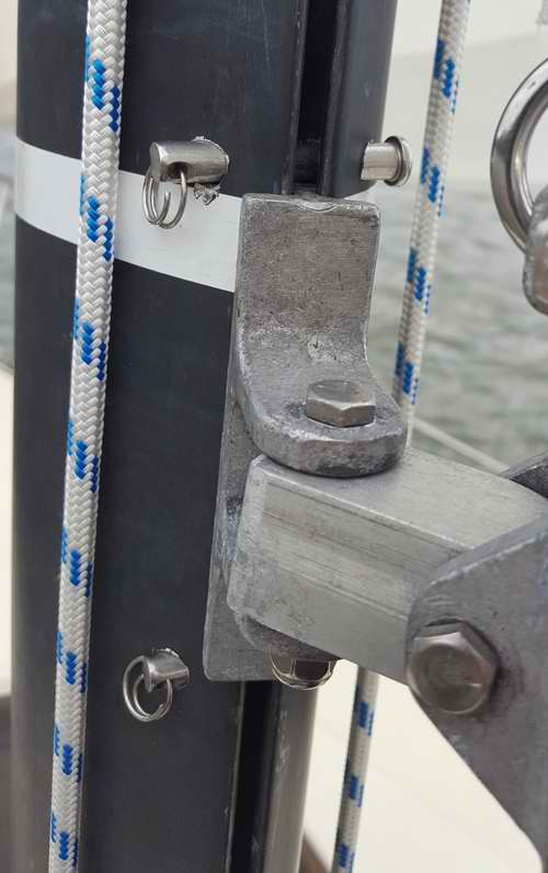
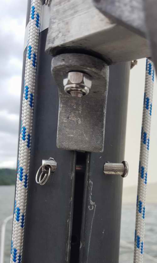
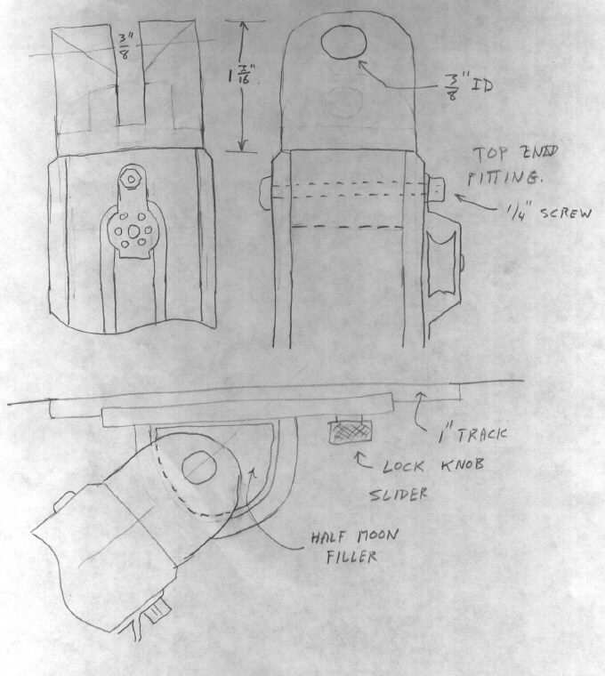 TOP
FITTING & BOOM SLIDE - A 1" sail track under the boom creates a
convenient attachment point for the top end of the vang and another
degree of adjustment. I used pop rivets with adhesive along the
bottom of a 2' long track. This
length increases the shear strength and creates more adjustment
points to lock the vang to. To create smaller adjustments I drilled
a hole between the existing holes in the track
TOP
FITTING & BOOM SLIDE - A 1" sail track under the boom creates a
convenient attachment point for the top end of the vang and another
degree of adjustment. I used pop rivets with adhesive along the
bottom of a 2' long track. This
length increases the shear strength and creates more adjustment
points to lock the vang to. To create smaller adjustments I drilled
a hole between the existing holes in the track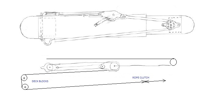 push of the 85 pound gas spring with the weight of the mainsail and sail cover on the boom.
The blocks are mounted against the outer tube so they don't interfere
with the sliding movement of the inner tube. Some commercial vangs incorporate an internal block in the top tube to equalize the
forces around the sliding junction of the tubes thereby keeping them in column to
prevent jamming. I installed my control lines on the outside, along
the bottom, and have experienced no problems with jamming. The V-jamb block for the control line is located near the top so I
can reach it with the boom pulled in while standing on the companionway
ladder. Placing it at the bottom of the vang would mean crawling too far forward on deck
to adjust it. The V-block also facilitates installation and removal of the vang at the ramp. See NOTE below.
push of the 85 pound gas spring with the weight of the mainsail and sail cover on the boom.
The blocks are mounted against the outer tube so they don't interfere
with the sliding movement of the inner tube. Some commercial vangs incorporate an internal block in the top tube to equalize the
forces around the sliding junction of the tubes thereby keeping them in column to
prevent jamming. I installed my control lines on the outside, along
the bottom, and have experienced no problems with jamming. The V-jamb block for the control line is located near the top so I
can reach it with the boom pulled in while standing on the companionway
ladder. Placing it at the bottom of the vang would mean crawling too far forward on deck
to adjust it. The V-block also facilitates installation and removal of the vang at the ramp. See NOTE below.