| SJ23 Tech Tip B06, (Updated 2021-08-13) Mike Raleigh, Bob Schimmel. | |||
|
Improve Centerboard Upwind Performance - Factory Flat Board. |
|||
|
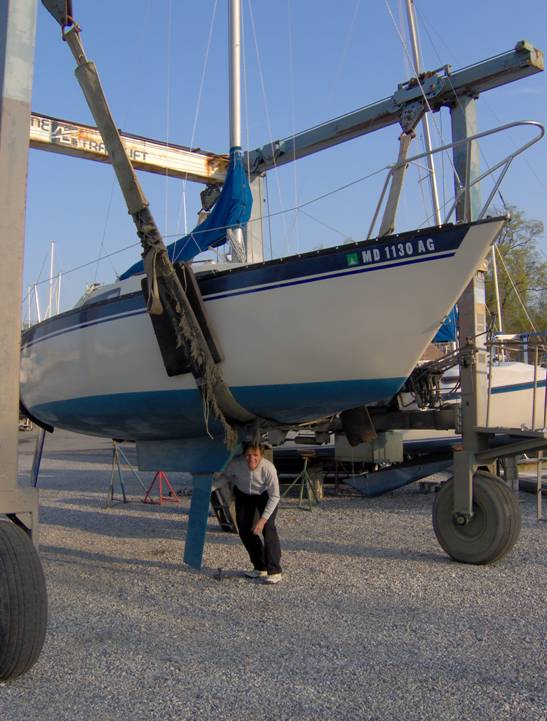
_______________________________ In anything under ~15 knots, our San Juan 23 carried a lee helm and made significant leeway, typically tacking through ~115° as measured on GPS tracks. When sailing close hauled she was slow. The usual fixes; mast raked aft, centerboard forward, and loaded-up main didn’t add up to a cure. While the heeling that accompanied stronger winds neutralized the helm, the tacking angle remained large. Slamming into a large wave induced involuntary falling off, recoverable only by substantial easing of the sails. Significantly, sailing under main alone resulted in weather helm and ~90° tacks. With the lee helm eliminated, the rudder no longer dragged the vessel downwind, overpowering the centerboard. With a nominal lead of 15.5% (the setback of the underwater center-of-resistance relative to the rig center-of-effort as a percent of waterline length) the boat should not see such poor balance, presuming the centerboard is doing its job as a foil. The stock centerboard for a San Juan 23 is a 3/8" thick flat steel plate that has a rounded leading edge and a short, tapered trailing edge. See Tech Tip B01. Using XFOIL, a popular two-dimensional airfoil analysis application (ref), to assess the flat board, we found it substantially wanting. It stalled in some conditions at attack angles of <3° which is well below the normal 5° to 7° of leeway for an SJ23.
______________ SOME THEORY _____________ FIG 1 below shows a graphical output from XFOIL for the stock centerboard under highly favorable conditions. XFOIL’s sophisticated treatment of boundary layer behavior allows it to model laminar-to-turbulent transition, separation bubbles, and stalling. Our simulated “highly favorable conditions” consisted of the following 3 criteria:
The solid trace in the graph shows as a function of distance aft from the leading edge. The suction on the windward side of the board (a dimensionless coefficient, Cp) on the negative scale versus the pressure on the leeward side of the board on the positive scale. The dotted lines represent an intermediate stage in the calculation. There is a high suction peak on the windward side of the board and a moderate pressure peak on the leeward side. Both peaks reach their maximums very close to the leading edge. This pressure distribution is typical for many airfoils (or hydrofoils). However, as we shall see from lift and drag data presented later, even this favorable case does not represent a good level of performance.
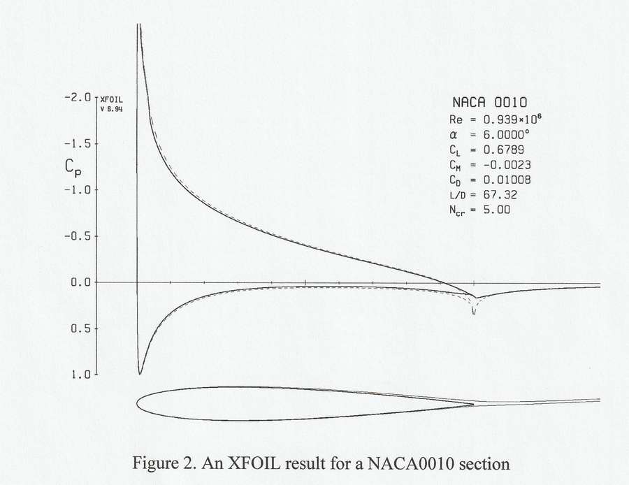
The lower portion of Fig 1 shows the board cross-section (aligned with the horizontal scale of the graph), the boundary layers on both surfaces, and the wake of the board. On the high pressure side of the board the boundary layer is thin and clings to the surface. On the suction side, however, the boundary layer is very thick. This leads to a wide wake, implying high drag. At lower speeds, without a deliberately tripped boundary layer, the flow completely separates from the low pressure side (stalls) for angles of attack of 3° or less. This results in low lift and high drag. FIG 2 - For comparison, Fig 2 shows the performance of a good upwind cross-section (NACA0010) under typical operating conditions. For “typical” we assumed non-polished board surface and forced transition to a turbulent boundary layer near the leading edge. The thinness of the boundary layers and the wake should be noted and as we shall see later, this section doesn’t stall until the angle of attack reaches 13.5°.
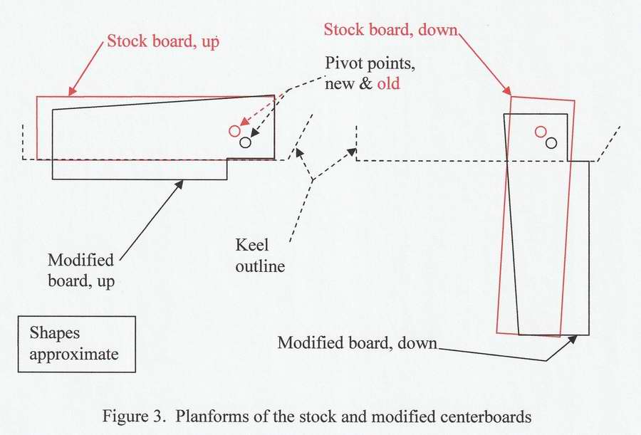
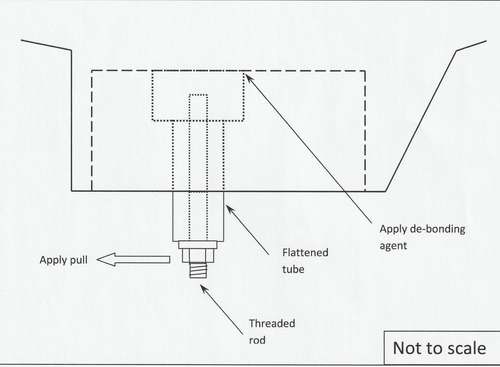
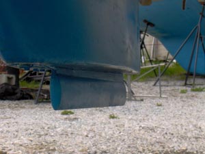
FIG 3 - There is nothing that can be done to improve the existing flat center board within the confines of the 1/2" wide centerboard slot. Although we tried, having previously faired the board to maximum thickness. We therefore altered the pivot location and planform of the board, as shown below in Fig 3. The alterations included adding an epoxy-on leading edge that protruded 3" from the slot with the board up. (A removable bracket holds the pivot pin of a San Juan 23. Changing the location of the pin involved modifying the bracket and re-drilling the board). These changes effectively shifted the lowered position of the board forward, helping to add weather helm. Furthermore, because it always protruded when up, we could thicken the leading edge of the board and improve the lift & drag characteristics. Finally, shifting the pivot point increased the gravitational moment holding the board down. This was particularly important as we used lightweight plastic for an epoxy-on nose.
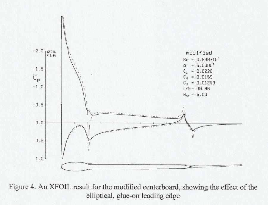
FIG 4 - After much experimentation with XFOIL, we chose to add a 3" by 1" elliptical nose to the leading edge of the board, as shown in Fig 4. Some of our previous fairing efforts show as a very slight taper on the back half of the board.
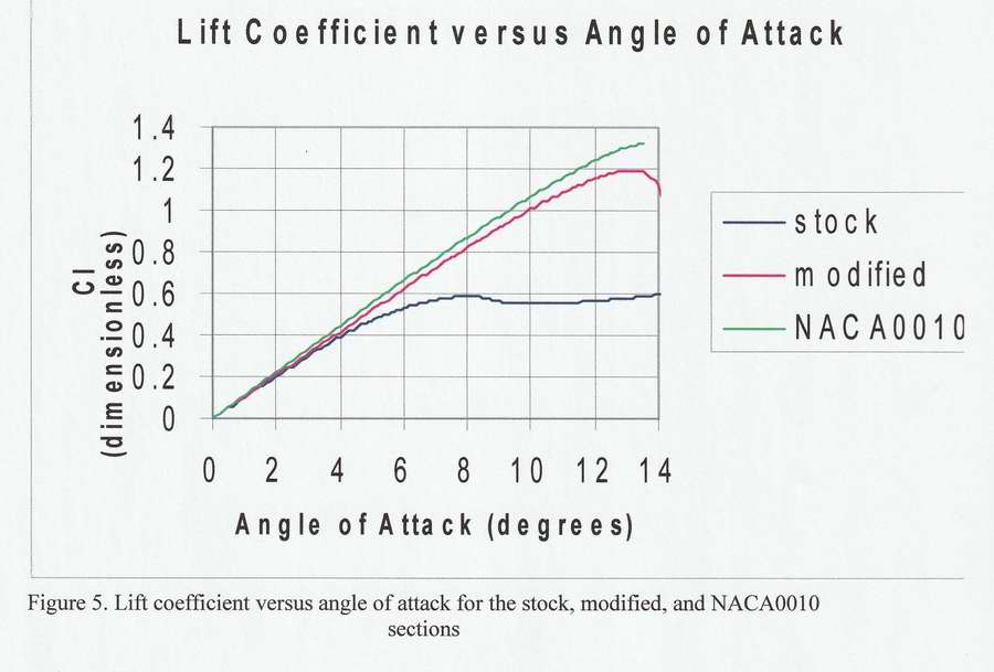
On both sides of this profile, a small separation bubble forms at the ellipse-to-plate juncture. However, the flow clings sufficiently to the ellipse to be re-directed at the plate, resulting in re-attachment of the flow. The thinness of the wake compares favorably with that of the NACA section. FIG 5 & 6 - The plots of lift and drag coefficients shown in Fig 5 and 6 provide a fuller picture of the performance of the stock, modified, and NACA sections discussed above. All the traces represent a velocity of 5 knots and forced boundary layer transitions. We take forced transition to represent typical operation since we have no intention of maintaining a polished centerboard.
All three lift coefficients (Fig 5) increase with increasing angle of attack but eventually reach maxima, beyond which they decrease. The maximum point defines the stall angle, beyond which flow grossly separates from the suction side of the foil and lift decreases. The stock, modified and NACA sections have stall angles of 8°, 13°, and 13.5° respectively. Even under the highly favorable conditions this data represents, the stock board produces less lift, at normal leeway angles, than the other two shapes. The other two shapes are reasonably close in performance. An angle increase of ~1/2° brings the lift coefficient for the modified board up to the same value as the NACA section. The drag coefficients (Fig 6) also increase with increasing angle and as stall is approached, increase dramatically. The stock board produces a very high drag, even at normal leeway angles. The other two shapes show virtually the same drag for normal leeway angles. The stock board is the clear loser in both Fig 5 and 6. If we do not force transition to turbulent flow, the stock board stalls at <3°.
_______________________________ CONSTRUCTION ________________________________
PIVOT POINT - In addition to moving the pivot point, we removed some material around the top of the stock board to accommodate the new positioning of the board in the slot.
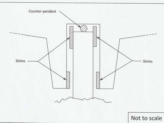
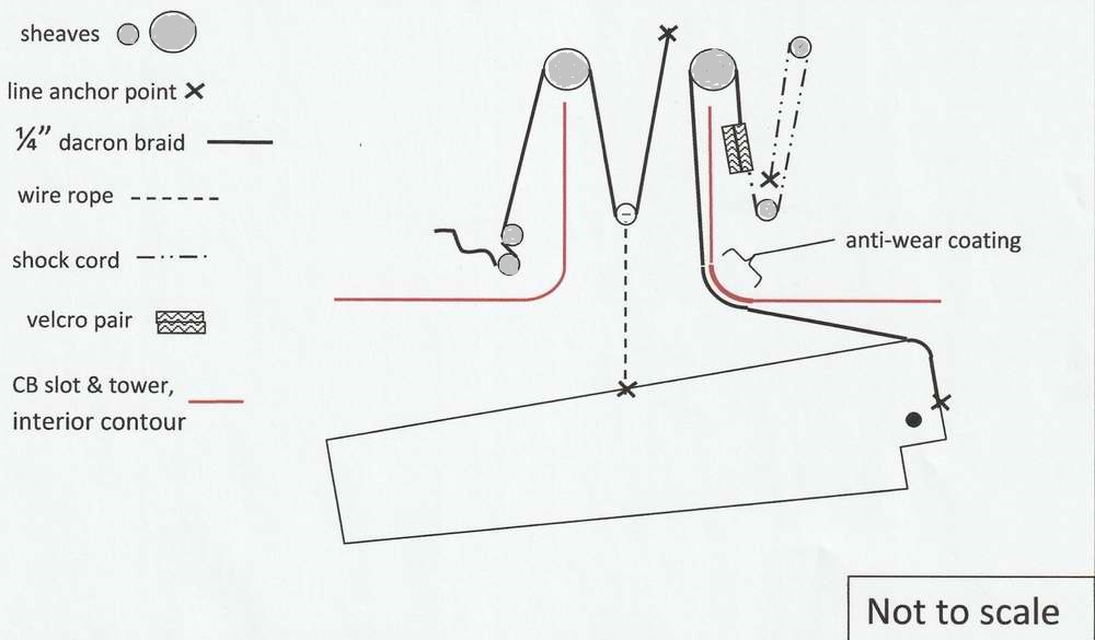
Although able to remain fully down in steady conditions, the board wants to swing when the boat pitched. As a cure, we added a “counter-pendant” to secure the board in the full down and forward position. We hold the cabin end of the counter-pendant with Velcro so it could pull loose for a grounding.
The addition of an ABS elliptical nose to a flat plate centerboard improves the lift, drag, and stall characteristics of the board. The penalty for this improvement is 3" more draft with the board up, increasing the draft from 1’11” to 2’2”. We found this acceptable. Other applications of this modification could include adding a nose to a flat plate rudder to improve steering authority. With the modified board we average ~95° tacking angles (as confirmed per GPS measured tracks), carry a neutral helm in light airs, and a light weather helm in moderate airs. This is a significant improvement over the performance with the stock board and we consider this modification a success. Qualitatively the boat seems to “fetch where see looks”, which wasn’t the case in the past. However, the mainsail only performance suggests that a little more weather helm would be advantageous. Accordingly, we may further modify the centerboard bracket to obtain the last iota of forward shift. Reference: Drela, Mark and Youngren, Harold, "XFOIL User's Manual". |
|||
|
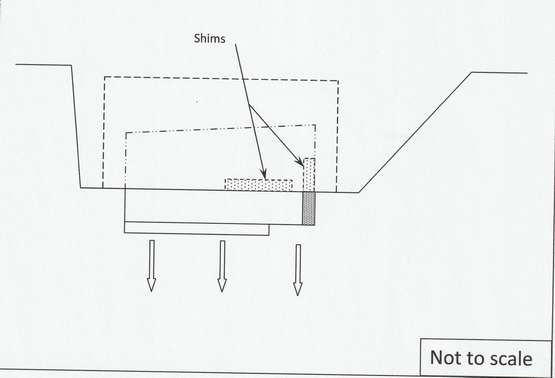
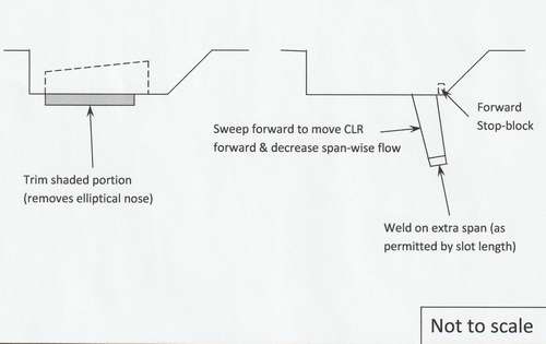
Some lost board area could be recovered and the aspect ratio of the board further increased by lengthening it to the maximum space permitted by the slot with a weld-on extension. Most
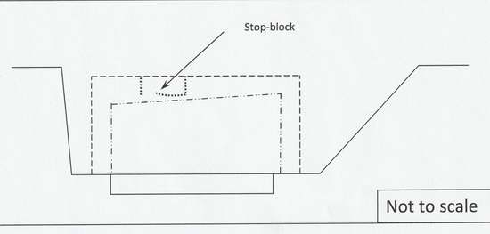
of the forward shift of the board would be lost in trimming away the protruding nose. However, retaining the counter-pendant would allow some forward sweep of the board, which would move the center of lateral resistance (CLR) forward and might diminish span-wise flow (reducing the tip vortex). The installation of an additiol forward stop block at the leading edge of the slot could prevent fiberglass impact damage from a too rapid lowering. |
|||
|
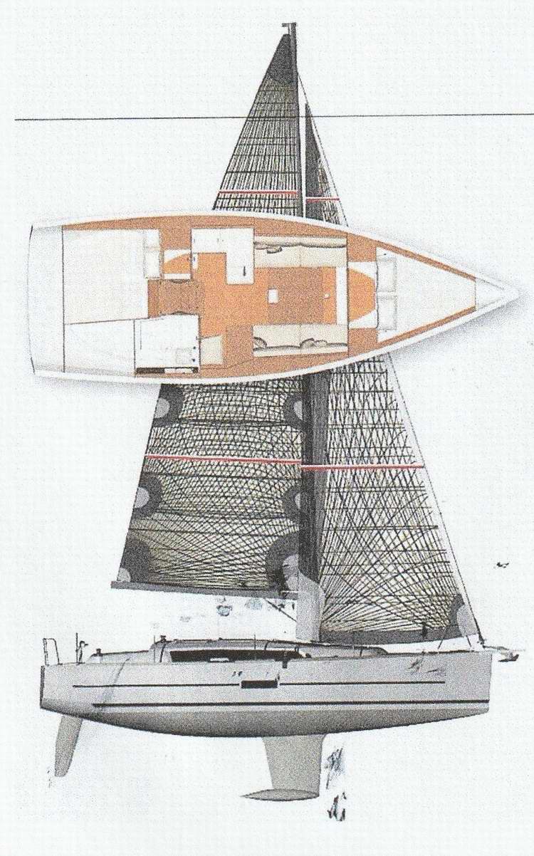
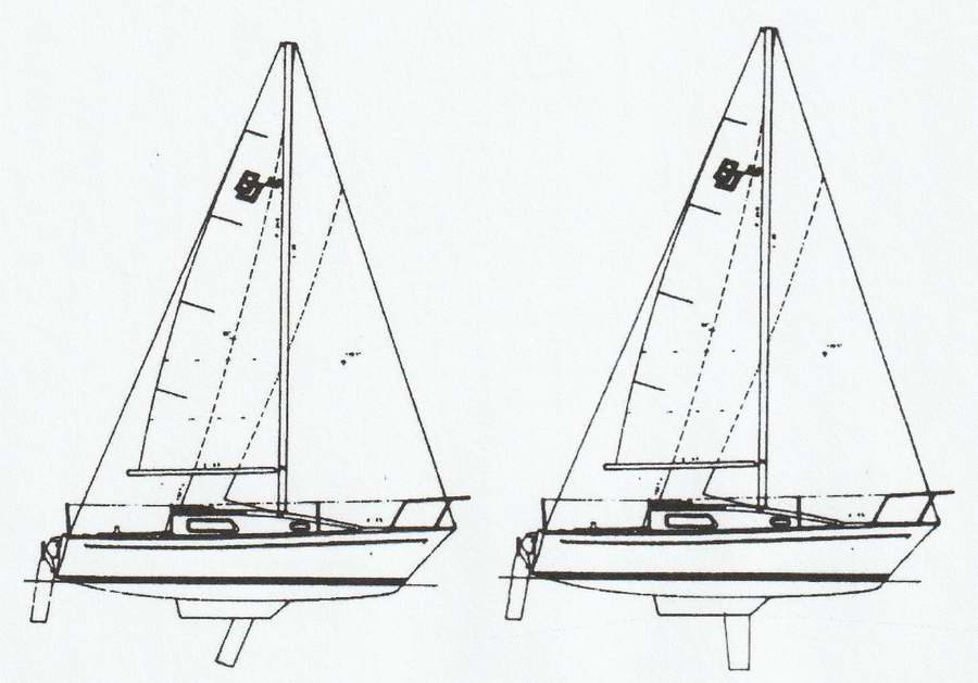
Where Should the Center Board be Installed? - In the beginning of this Tech Tip I mentioned lead percentage as a guide to keel/center board positioning. A look at some modern fin-keel designs would suggest a simple rule of thumb, wherein the fore-and-aft position of the keel should place the leading edge nearly in line with the trailing edge of the mast. An example of this is the Dufour 360 shown below.
Consider then a San Juan 23 (MKI) with the stock center board and the same San Juan 23 with the modified center board. Which center board looks right? In answering, remember that the stub keel is so small and has so low an aspect-ratio as to be virtually non-existent as a lift generator. So it’s all up to the flat centreboard then?
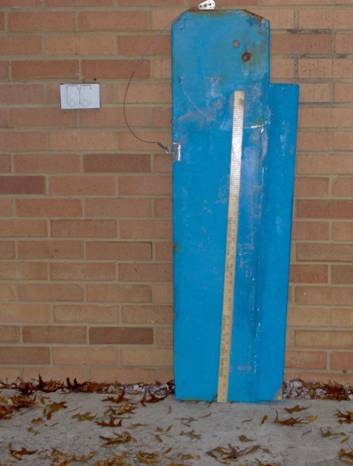
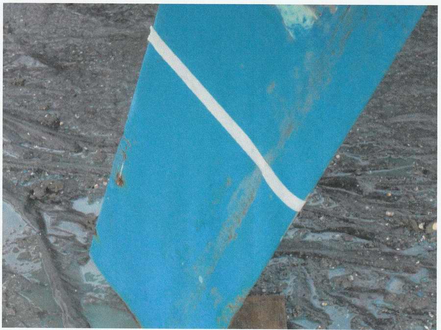
Modified Center Board Draft Line - Here’s a photo of the modified center board with a temporary masking tape “draft line” to visualize the shape.
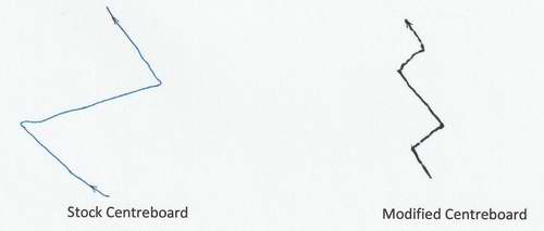
Sailing Performance with a Modified Center Board - So its all fine and dandy that XFOIL calculates better performance, but what are the results when sailing? Below are some “close-hauled” ground tracks traced from the display of a GPSmap76. The X and Y scales are equal to display sailing angles correctly. We did not alter the X-to-Y ratio in reproducing these tracks. This is quite an improvement.
On the Race Course - Once the board was “modified” we went from last-in-fleet finishes during Wednesday night races to mid-fleet finishes. Among similar size boats our SJ23 could stay close to a Catalina 22 (this crew was a good at chasing light-air puffs and tacking downwind) and the San Juan 21 (weighs nothing, dry sailed, polished Balto-Plate bottom, new “black” racing sails, totally retractable keel, a phenomenal light-air boat). We generally beat the Mirage 24 (think C&C 24) upwind. We also occasionally beat a C&C 29 with wretched cruising sails. If a “free” Sabre 28 hadn’t come along to replace our SJ23 our next move was to replace the 40+ year old, tissue-thin, stretchy main sail. But that’s another story.
FINAL COMMENTS For me, a San Juan 23 checked many important boxes:
I only had two things I needed to fix on my SJ23.
------------------------------------------------------ References -------------------------------------------------------------
|
|||
Hmmmm. Bob Schimmel. |
|||
|
Return to Tech Tip Index. . . . . . . . . . . . . . . Have a Question? |
|||
 INTRO - Mike emailed the results of his 2011 investigation to preserve it for public use. He wanted others to benefit from the knowledge. He has since sold his SJ23.
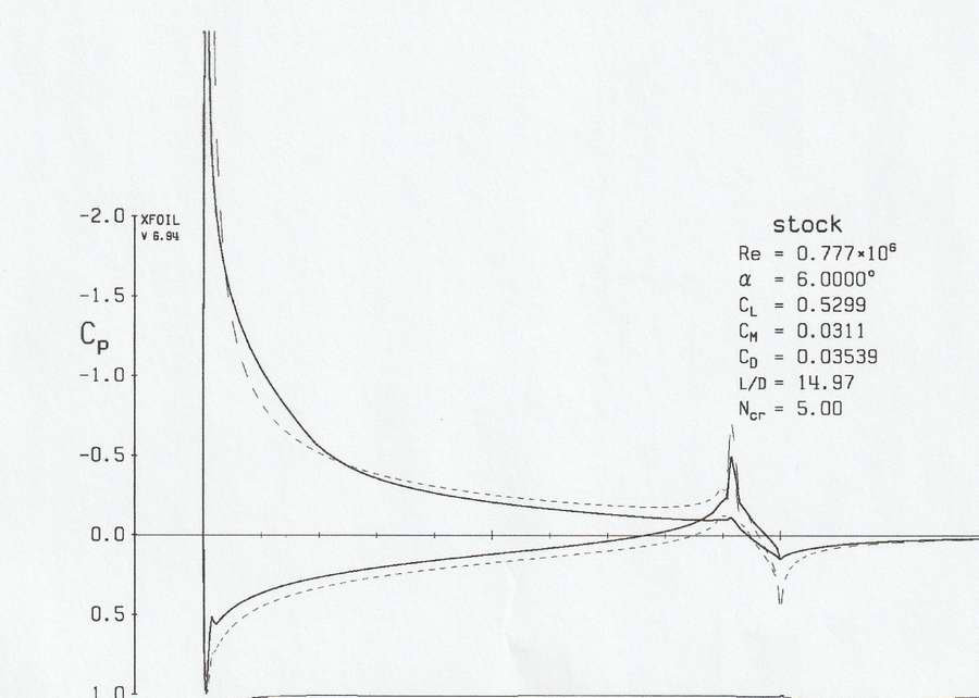

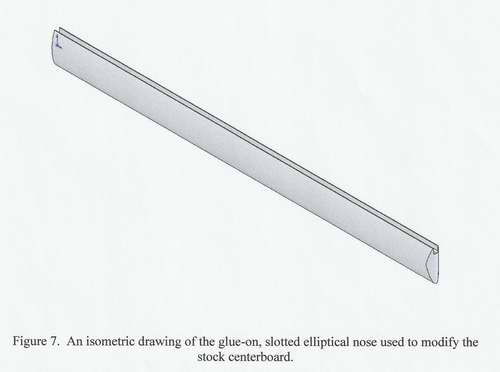 ELLIPTICAL NOSE - The elliptical nose shown in Fig 7 is made of
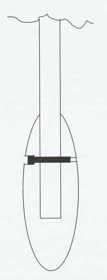
 How Do You Get the SJ23 On/Off the Trailer? -