SJ23 Tech Tip B09, (Updated 2024-02-06) Bob Schimmel

Index

Rudder Repair and Dimensions.

INDEX  - Rudder Head, Rudder Shell, Replace a Pintle, Transporting a Rudder, Leaking Gudgeon, Propeller Damage.

There are many ways you can loose the rudder or damage the blade. Below are some popular ones.  Take your pick! 
  1. PINTLE LOCK - The factory rudder lock on the pintle can let go and the whole works will slide overboard unless you are lucky enough to be holding on the tiller at the time.  Don't worry, the foam filled rudder floats!  Of course steering a sailboat without a rudder is another matter!  Sorry, you're on your own here for retrieving it.  Take the sails down and use the engine.  See Tech Tip B10
  2. IMPACT DAMAGE - One sure way to break a blade is to hit an underwater obstacle with enough force to damage it beyond recognition.  No point in going back for it, but you should go back there to clean the mess!  If this is the case you've likely done significant damage to the transom and your first course of action should be to seal the hole and head for shallow water.  You do carry duct tape, soft wood plugs and epoxy putty don't you!  
    It should be noted that hitting the bottom with the rudder blade is unlikely since the center board is lower than the rudder, unless you are sailing with the center board up!  Never discount Murphy's Law!  Solution
  3. PIVOT NUT - If you have a kick-up rudder and want the added security of not loosing the blade to the briny deep, then wire the nut on the pivot bolt to lock the assembly in place.  Drill a 3/16" hole through both the nut and the bolt and insert a cotter pin or run stainless steel wire through it, twisting the ends together around the nut.  This has the added feature of maintaining the correct spacing and hence friction between the blade and the rudder head.  More info below.
  4. BLADE DELAMINATING - If water penetrates the fibreglass shell then eventually the foam core will detach from the shell.  Water can penetrate the shell at each bolt hole or a fibreglass crack.  Notice the rust on the aft pintle mounting bolt at right, a sure sign of leakage there.  While a leak usually occurs after years of sailing and/or leaving the blade in the water, occasionally it happens to a new rudder.  Delaminating alone should not result in a break since the shell has significant form strength.  It should also be noted that the rudder should be fine as long as the foam is firmly attached to the shell.  However, one day the blade may snap off clean from a load that the shell alone cannot support!  When the boat is turned rapidly at hull speed or in big waves, there is a lot of torque load on the blade.  The break usually happens at the lower pintle mount as shown at right or just below the rudder head.  Nasty. 
    - This is a known problem for which there is a simple solution; install a compression sleeve around each bolt that goes through the rudder. 
    Drill out the bolt hole to 1/2" oversize.  Plug one end with tape and pour in the epoxy.  Let cure 24 hours and drill out the center of the plug to the correct size, creating a tube between the shell sides.  This tube seals the inside of the bolt hole to keep water out and bonds the sides of the shell together to add strength.  But you should also check the blade regularly for small cracks to prevent water leaking through the fibreglass.  Don't delay this job.
    - This problem is a prime example of why the majority of hulls, including San Juan, use solid glass below the water line instead of foam or wood core.  Too bad Clark didn't seal the rudder holes.  This is an excellent reason to lift a kick-up rudder blade out of the water when the boat is on a mooring or at anchor.  Besides, the boat hunts less. 
  5. PROPELLER GOUGES - Another sure way to damage the blade is to turn the rudder far enough so the blade touches the outboard propeller.  If the engine is running you will "nick" the blade with the efficiency and quickness of a lathe!  Do it often enough and you will cut right through the fibreglass shell and create a water logged blade.  There are a myriad of other situations in which this can happen so I won't bother to describe them all.  Fortunately there is a solution to avoid this.
  6. THEFT - And last but not least, there is always theft.  Although why anyone would steal a rudder is beyond me, but it has been done.

MAINTAIN THE INTEGRITY OF THE RUDDER SHELL - The key element to rudder longevity and impact survival is to maintain the integrity of the shell.  The factory rudder is made from two symmetrical fibreglass shells glued together along the edge with a core of closed cell foam inside.  You can see the joint by examining the edge of the rudder, there is a slight overlap. 
There are two rudder designs; kick-up and fixed blade.  Both designs suffer from a common manufacturing flaw in that the inside of the bolt holes are not sealed and there is no compression strength to prevent over tightening the bolt.  With time the water ingress detaches the closed cell foam from the shell, reducing the structural strength.  The second problem with this assembly is there is no compression strength around each bolt hole to prevent over tightening the nuts to compress the shell.  The foam has little compression strength and stress cracks will develop in the shell as the rudder is flexed under steering load.  The combined effect of these two problems weaken the shell and lead to an inevitable break along the cracks. 

Once you understand this problem it should not come as a surprise!  The best way to solve it is to install an epoxy compression sleeve inside each bolt hole as depicted by the green epoxy in the kick-up rudder drawing at right. 

KICK-UP RUDDER PIVOT HOLE - The sketch at right shows a cross profile of the kick-up rudder head equipped with an epoxy compression sleeve bonded inside the blade (green) and a bronze bushing (brown) inserted to keep the plates of the rudder head apart.  The gap shown between the blade and the rudder head is exaggerated.  In reality the gap is barely there, to eliminate steering slop.  The tiny gap is maintained by the slight protrusion of the bronze sleeve. This gap is about 1/16" and ensures easy pivoting, minimal side play and no compression of the blade shell.

Find a 1/2" ID bronze bushing with a (minimum) 1/8" wall thickness that fits snug over the pivot bolt.  A thick wall bushing is better than a thin wall.  Bushings are available from a bearing supply house.  Ream out the hole in the blade so the bushing just slides through.  Dry fit the bushing to confirm that it aligns with the rudder head and there is free pivot movement of the blade.  Then form an epoxy compression sleeve inside the rudder blade by using a Dremel tool (or similar) to gouge out 1/4" of foam from inside the pivot bolt hole.  Replace the gouged out foam with epoxy thickened with carbon graphite powder (peanut butter consistency), effectively forming a tube of slippery epoxy that bonds both shells together.  This is your epoxy compression sleeve that also seals the foam core.  It is OK to slightly overfill the hole.  Smooth and form the inside of the wet epoxy by inserting the bushing.  If you lightly coat the bushing with some wax, release agent or cooking oil it can't stick to the epoxy.  Let cure for 24 hours.  Once cured, remove the bushing and cut the length to about 1/16" longer than the
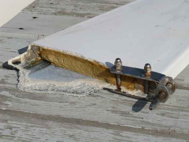
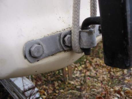
 thickness of the blade. 
Tightening the pivot nut squeezes the rudder head against the bushing, not the blade.  The slippery epoxy compression sleeve turns around the bronze bushing.  This technique permits you to tip the blade up/down with minimum friction or side play.  It takes a bit of fiddling to shave the end of the bushing to the correct length to minimize the side play of the blade but it ensures long life. 
Similarly seal the inside of the hole that the bungee cord goes through.

FIXED RUDDER PINTLE MOUNT - Similar to above, if you have a fixed rudder, install an epoxy a compression sleeve through the rudder at each pintle mounting bolt.  This prevents crushing the rudder and seals the rudder shell to keep water out.  It adds a tremendous amount of form strength which is very important on the fixed rudder.  Use a Dremel tool to gouge out 1/4" of foam from inside each bolt hole.  Replace the gouged out foam with thickened epoxy (peanut butter consistency), effectively forming a tube of epoxy that bonds the shells together.  It is OK to slightly overfill the hole a bit.  Smooth and form the inside of the wet epoxy by inserting the bolt.  If you lightly coat the bolt with some wax, release agent or cooking oil it can't stick to the epoxy.  Let cure for 24 hours.  The epoxy sleeves guarantee you won't be able to crush the shells together. Install a similar sleeve for the tiller bolt.   top

ALUMINUM RUDDER HEAD - The rudder head of a kick-up rudder is made of 1/4" thick aluminum plate.  All joints are welded and all sharp corners are rounded off smooth with a grinder.  The wood spacer isn't shown in these diagrams, but it is positioned at the back of the rudder head with the top aligned even with the upper pintle.  You can see it better in Tech Tip B10.  It's purpose is to create a uniform gap between the two sides of the rudder head and to limit the up swing angle of the blade.  top


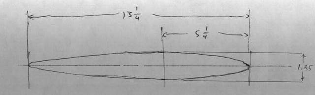
The dimensions are shown in inches.  The sketches are NOT to scale but they are fairly accurate.  The dimensions for the fixed rudder, are the same as the  overall dimensions of the kick up rudder. 


If you don't have the ambition to rebuild a broken blade or build a new rudder, then San Juan Sailboats (Stephen Jensen) makes a replacement rudder that has a thicker shell with lighter foam.  I told he will guarantee them for at least two years.  Send your order to.


The sketch below is a close approximate of the cross profile of the blade.  It's very difficult to copy a full size blade in this dimension. 

REPLACE A PINTLE - If you loose a pintle from its mounting strap, it can be replaced with a 3/8" stainless steel bolt or rod.  Choose a bolt that has at least 3" of unthreaded shank.  Grind the threaded end of the bolt to a slight taper to aid inserting it into the gudgeon.  Cut the bolt to 3" long.  Make the bottom pintle at least 1" longer than the top one to aid in installing the rudder on the transom.  You'll appreciate this once you are on the water.  Drill a 1/8" hole through the side of the pintle mounting strap and the bolt.  Insert a 1/8" bolt and nut or a roll pin through both to lock the new pintle in place.  Use a liberal amount of sealant between the pintle and the strap to lock the bolt in place and minimize movement.  You don't want a sloppy fit.  While you're at it, drill a 1/8" hole across the end of the pintle (just below the gudgeon) so you can use a hair pin or cotter pin to lock the rudder to the gudgeon.  That silly little factory stainless steel retaining spring on the gudgeon is a joke.  The slightest bump against the rudder and the spring lets go.  So install a heavy duty hair pin.    top
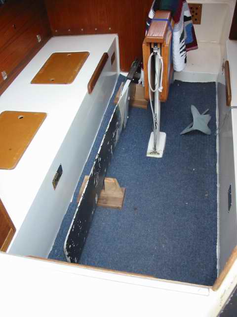
RESEAL A LEAKING GUDGEON - Can't find the source of the leak in your hull and looked everywhere!  Try the gudgeons.  They take a lot of abuse under the strain of sailing and the sealant ages, breaks free in about 7 years, causing a slow leak.  Another source of leaks in the cockpit drain line fittings.  Treat all seals as if they are below the water line.  Use a liberal amount of butyl rubber or Sikaflex under the gudgeon plate, around the bolts and under the washers.  Wipe off any excess with acetone to prevent that amateurish look.  About the only way you can damage a gudgeon is to back the boat into something or if the rudder blade bounces off the bottom.  In either case the hull requires inspection for cracks and the gudgeons will likely have to be resealed. Do not over tighten the nuts to prevent crushing the hull or squeezing the sealant out.  top


TRANSPORT A RUDDER - A rudder isn't exactly light, the shape is awkward and the surface is slippery when it comes out of the water, which doesn't lend itself to easy storage.  However, if you make a couple of wood support brackets (show at right) the rudder can lie on the cabin floor where it will stay put.  It never rubs against the cabin wall when traveling down the highway and is perfect for winter storage.  
That's my home made 2 lb. baby Bruce anchor on the floor!  It can actually hold Panache in about 5 knots of wind.   top

PROTECT A RUDDER FROM PROPELLER DAMAGE - Propeller gouges in the blade should be tended to immediately before water can soak into the foam core.  This is another one of those good reasons for carrying a roll of duct tape on the boat.  This tape will stay attached underwater provided it is applied to a dry surface so you can at least get home without fear of the foam core saturating with water.  Once you arrive, use the standard techniques of cloth and epoxy covered with gel coat to do a permanent repair.  Duct tape (mach III tape in the US and Mach IV tape in Russia!) doesn't last forever, despite what some people will tell you! 

There are several techniques to protect the rudder blade from touching the propeller: 

  1. Move the engine further back so the rudder blade turns in front of the outboard.  However, this also squats the stern more when under power. 

  2. Raise the engine.  Problem with this is it will reduce the thrust which you need in steep waves.  You don't want the prop to come out of the water.  An occasional lift out is OK.

  3. If you have a Tiller Tamer, tie a knot in the friction line to limit the turning angle of the rudder.  Alternately you can locate this knot at the optimum turning angle of the rudder to prevent stalling the blade!  Great for racing. 

  4. Install a propeller guard on the outboard engine.  The guard consists of a stainless steel ring that fits around the propeller on a outboard engine.  It is designed to decrease the risk of a propeller cut for humans and marine animals.  On an SJ23 it can also keep the propeller from touching the rudder, thereby protecting both.  Guards come in two styles; a wire cage or a stainless ring.  I like the ring because it incorporates some hydrodynamic principles to increase the thrust.  In a really efficient design the thrust increase can be up to 30%.  Be sure to size your ring so it leaves at least a 1" gap between the tip of the propeller and the inside of the ring.  They are available in many chandlers. See Tech Tip D06 to install a ducted propeller.  Check this link for design ideas.

  5. Install a flat aluminum strut on the side of the engine leg.  Make it long enough that it stops the rudder from touching the propeller and align it with the water flow so it doesn't create turbulence.    top

And that's about it for the rudder.
 

UPDATE  FACTORY CONSTRUCTION - I'm hoping that the small parts tooling is still around in Gene's back yard or in western Washington somewhere.  The days get foggy with age or too many styrene fumes coming from the Clark laminating shop.  If the tooling is still around, I could draw up the lamination schedule for a rudder and a real part could be built.  Gleno.
 

Mould Layup

Assembly

1 - Spread gel coat in each mould and let cure. 1 - Bolt the 2 mould halves together.
2 - Lay in 3/4 oz mat, wetted. 2 - Pour 2 part urethane foam in the core void through the opening in the top of the mould.  (use 8lb/cubic foot density foam).
3 - Lay in 18 oz roving, wetted. 3 - Trim off the excess foam at the top of the rudder and detail the edges.
4 - Use thitropic putty at the edges of the 2 halves to stick the 2 parts together. 4 - Install 2 Ronstan pintles.  Bolt them through compression tube sealed holes.


BUY A RUDDER - An off the shelf kick up rudder you can buy.  Pricy but good.  The blade is larger than the factory version that can hold the boat from rounding up when over powered.  I like the way the blade can fold up to vertical.  You might actually be able to tow it down the road with the rudder on the transom.

    https://store.ruddercraft.com/index.php?route=product/product&path=182_62&product_id=862
 

Return to Tech Tip Index. . . . . . . . . . . . . . . Have a Question?