| Ever noticed water pooled at the bottom of the port cockpit locker and wondered
where it came from? Well there are several possible sources; cockpit thru-hull fittings, gudgeon bolt
holes, toe rail screw holes,
toe rail deck seal, transom moulding, water overflowing the port locker
lid gutter, scupper holes and a myriad of other minor things I haven't found
yet. The port locker gutter will overflow
on a long starboard tack if enough rain falls on the seat or if you dump a bucket of water on it. There are better designs on other boats but you'll have to live with this one, although many people have sealed their lid to solve this problem. If water has filled the "mini sugar scoop", under the cockpit just behind the aft cockpit bulkhead support, it's a sure bet that you have a leaky gudgeon bolt hole, cockpit or transom thru-hull fitting. On the other hand it could be something minor like the back stay chain plate or the transom moulding. Either of these problems can take on a whole new dimension if the leak goes beyond a dribble! This leak is not a problem to shove to the back shelf while you idly sip your beer in the shade. For example, an open thru-hull fitting can sink an SJ23 in ~10 minutes.
Not a lot
of time to do something about the problem is it? Since all of us
should adhere
to the principle that prevention is better than cure, it is best to check
the integrity of the cockpit drainage system on an annual basis. NOW
would be a good time, since your boat is out of the water!
 The cockpit
sole of an SJ23 is sloped aft slightly so water and debris
can flow to the drain holes, back into the "drink" where
it belongs. This helps to keep the cockpit sole in front of the companionway cleaner,
which does likewise for the cabin sole. The cockpit
sole of an SJ23 is sloped aft slightly so water and debris
can flow to the drain holes, back into the "drink" where
it belongs. This helps to keep the cockpit sole in front of the companionway cleaner,
which does likewise for the cabin sole.
In the original version of the SJ23, the factory installed the
cockpit fittings directly above the hull fittings with a vinyl tube
connecting them a shown at right.
This design is questionable as it is difficult to install the vinyl
tube, check
the hull fittings or seal them properly in the cramped space under
the cockpit.
I just know the "little kid" in the shop
was saddled with this job!
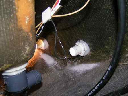
How to do the cockpit crawl. Unfortunately, the port drain fitting was poorly aligned on Panache (Hull CLKJ0109M77K), which kinked the vinyl tube,
creating a
strained installation and questionable seal. You can see the sealant separated from the hull
at right. Its too bad this is such a poor photo taken in 2008. It is a difficult place to take one and I have since replaced this fitting so can't retake the photo.
This fitting installation looks factory original and I know that the previous owner never worked on it. (The black and white wires go to the stern light). As another example Jim's slightly later SJ23 (Hull CLKJ0157M78A) had a fairly straight vinyl tube between the port fittings. Both boats were made in the Pacific NW from the same mold so I think Clark may have fixed the alignment in the mold.
In the later Mk I hulls and all the Mk II & III
hulls the factory solved this problem by installing the drain holes through the
transom as shown below. A transom drain is easier to
install as alignment of fittings is relatively easy. In addition, the fittings will not be under stress
as vibration of the hull is absorbed over the flex of the 1' long drain hose.
This ensures that all seals stay
water tight and you have peace of mind. There are other
advantages to the transom location. Read on:
- Drain speed - The cockpit drains much faster with the exit
holes above the water
line as the hoses will seldom experience back pressure.
- Plug a fitting - It is easier to plug a thru-hull fitting
on the transom than under the hull. You can reach the fittings looking over the transom and keep your
head above water to do this job.
- Water gurgling into the cockpit while motoring - The
narrow stern of
an I.O.R. designed sail boat will squat under power or high speed
sailing due to less reserve buoyancy back there. But with the
drain fittings above the water line, there should be minimal to no water
flowing into the cockpit. The only time I have experienced water coming in is when sailing fast downwind (8+ knots) in big waves. What a ride.
- Improved flow dynamics under the hull - The resistance of
water flowing past an open hole below the water line is
eliminated. This is
a minor issue at hull speed but every bit counts when ghosting. See NOTE 2
below.
- Two fewer holes at the water line to sink the boat - The
transom mounted fittings will be at least 4" above the water line
instead of at the water line. See
Note 1 below. This has to create peace of mind.
- Maintenance can be done with the boat floating in calm water.
On the other hand the "little kid" could have quit working for Clark!
These reasons alone should be enough to
upgrade your cockpit drain fittings, but if you are looking for
another, how about being able to drink your rum in peace! Personally I hate a hull fitting that is below or at the water
line, especially when it's so simple to install one above
the water line. A fitting that is below the water line has a higher likelihood
of failure, with
obvious catastrophic results. This is a real concern for those boats
that float year round. NOTE 1: To elaborate on point 2 above,
(the most important
reason of all) you should consider how
difficult is it to plug a thru-hull fitting if a hose or fitting were to break?
I can
tell you that it is next to impossible to shove
a wood plug into a thru-hull fitting installed under the cockpit, especially if
the boat has already started to sink. It is pretty well impossible to reach the fitting from the surface. What complicates the job is that you are working
blind, searching over quite a big area to find the fitting. You can take
warmth in the fact that you will improve your chances of finding
the fitting if
you jump in the water with plug and hammer in hand. Doesn't sound appealing does it?
Plugging
the hole from the inside isn't much better either. The tight confines in the locker
may lead to your demise in the urgency of the moment while it fills with
water! This will take only 5 minutes. I'll let you use your imagination here! On the other hand, with the thru-hull fitting at the bottom of
the transom, it is much easier to reach down the outside to plug the hole, even with the hull half submerged.
You can also monitor the plug while under way, putting your fears to rest.
Don't have a tapered wood plug? Use the most handy
bathing suit you can find!
NOTE 2: - Each thru-hull
fitting is installed in a depression so the top of the fitting fits flush with the hull
or the cockpit sole. This
is a clever design that extends the full 1/4" thickness of the fibreglass right
under the lip of the fitting, creating the strongest possible installation
with minimal cost. The lock nut tightens against a full ring of fibreglass. The flush fitting also means the cockpit can drain drip dry and
the water on the outside flows by smoothly.
 CONSTRUCTION
(2008)
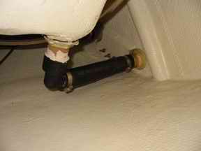
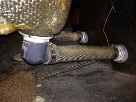
- The cockpit drain plumbing shown at right belongs to a Mark II SJ23. The San Juan factory used the same 1.5" Delrin thru-hull fittings
throughout the entire
production of the SJ23, 24, 7.7 & 28 hulls. Likely other models as well.
The transom of the SJ23 Mk II shown at right is reinforced with two angled half rounds of
fibreglass (port one shown) and another imbedded filler across the bottom to support the lower gudgeon. Together they restrict where the
transom drain fitting can be installed. I think it would have
been better to install a 3" wide filler across the bottom so the thru-hull nut can be supported all around, but that's me. The transom of an SJ23 Mk I is not reinforced across the bottom. CONSTRUCTION
(2008)
- The cockpit drain plumbing shown at right belongs to a Mark II SJ23. The San Juan factory used the same 1.5" Delrin thru-hull fittings
throughout the entire
production of the SJ23, 24, 7.7 & 28 hulls. Likely other models as well.
The transom of the SJ23 Mk II shown at right is reinforced with two angled half rounds of
fibreglass (port one shown) and another imbedded filler across the bottom to support the lower gudgeon. Together they restrict where the
transom drain fitting can be installed. I think it would have
been better to install a 3" wide filler across the bottom so the thru-hull nut can be supported all around, but that's me. The transom of an SJ23 Mk I is not reinforced across the bottom.
What follows are the issues and requirements of each component of the
cockpit drainage system, going from top to bottom. After all, "shit flows
downhill". Also read the Safety Notes
section at the bottom as there are some good points regarding freezing.
The outside of these thru-hull fittings are equipped with a two opposing notches to facilitate
install/removal. The fitting also has a cross pin to block things from slithering down! You can
grip the notches with a purpose bought thru hull tool or fabricated one from a
12" long length of (2 x 1/8)" flat iron. Cut the corners
of the flat iron off at 450 so they fit into the notches and cut
the end off to make room for the cross pin inside the fitting. Insert
the tool into the flange till the bevelled corners rest in the two notches.
Press the tool down firmly to prevent
the fitting from turning as you spin the nut off. A tool like this is the only
sure way to guarantee that you won't break the fitting or ruin the seal as
you spin the nut.
GUDGEON BOLTS - The
four bolts that you see at the bottom of the transom in the photo above
secure the bottom
gudgeon. You may as well reseal all of them while you are
under the cockpit! These bolts can take quite a beating
over the years and are likely the other source of some of the leaks.
They must "complain" like heck every time you "touch"
the bottom with the rudder!
It wouldn't hurt to soak the holes in epoxy to reseal the
fibreglass.
NOTE: It should be OK to reseal these bolts with the boat afloat in calm
water, provided the
rudder is off during the cure stage. If the waves start lapping against
the fitting during the
cure that is OK, as Sikaflex or butyl rubber actually cures a bit quicker with water splashed
on it. You're call.
COCKPIT FITTING & ELBOW
- Reuse your recessed cockpit fittings if they are in good condition. If it has weather damage or even one tiny stress crack,
replace it. Fact is, if you think it will break when you hit it
with a (2x4)" then it should definitely be replaced. Gene Adams used a stainless steel sink basket as a replacement for the cockpit
fittings, claiming they hold up very well. Sink baskets are equipped with 1.5" pipe
thread so you can screw on an ABS plumbing elbow. They are available at
most any retail plumbing
store, not your favourite chandler!
The black elbow adapter
shown above and to the left is a standard ABS plumbing fitting, (1.5" MPT thread to barb) that is
 required to
direct the drain 900 aft towards the transom. To facilitate assembly of the two, cut the barbed end and
1/4" of thread off the cockpit fitting and file the end smooth. In the photo above very little of the barbed end was
cut off the cockpit fitting. If all the barbs are cut off,
leaving just the thread, then the elbow fitting will cover most of the
thread and position it a little higher for faster flow. Dry fit
all components in the drain system. required to
direct the drain 900 aft towards the transom. To facilitate assembly of the two, cut the barbed end and
1/4" of thread off the cockpit fitting and file the end smooth. In the photo above very little of the barbed end was
cut off the cockpit fitting. If all the barbs are cut off,
leaving just the thread, then the elbow fitting will cover most of the
thread and position it a little higher for faster flow. Dry fit
all components in the drain system. Sanitize and seal the recessed hole in the cockpit
sole. Position the cockpit fitting so the cross pin is aligned fore/aft.
This should go a long way towards preventing debris
from accumulating over the pin and plugging the fitting, similar to hair
in a sink drain. See NOTE 2 below. Tighten each nut
fairly snug,
not tighter. Sealant must ooze out all around the flange to ensure a water
tight seal. Seal the thread with one layer of white Teflon tape and
screw the elbow adapter on, pointing the barbed end to its respective
fitting on the transom.
TRANSOM THRU-HULL FITTINGS - If you are careful in your measurements, you can position the height of the transom thru-hull fittings so
the hoses slope down slightly (same slope as cockpit sole) with the boat floating level. This lets them drip dry for winter storage, preventing ice damage, and prevent a new "life form" from taking hold inside. This is easier said than done but very necessary.
HOSE SLOPE
- To
mark the vertical position of the transom fitting, extend the bottom of the cockpit
elbow to the transom with a long straight stick. Mark the spot on the inside of the transom. Place the magnet of an automotive magnetic pickup tool against that mark on the transom. Then use a magnetic compass outside the transom to point to the magnet. Mark the spot on the outside of the transom. This is the bottom edge of the hole to be drilled through the transom. This location on the inside of Panache's transom had sufficient clearance from the bottom and all around to tighten the fitting nut
against a seat. I wanted the nut to be seated uniformly all around.
HORIZONTAL POSITION
- While the marks previously placed on the outside of the transom basically determine the location of the fittings, to accurately mark the horizontal position, I sat in the cockpit and looked down over the transom. The thru-hull fittings should sit ~3/4" inside the cockpit
floor fittings for slightly better flow. The
factory installed the fittings just above the turn of the
transom. Using the inside of the fitting nut as a guide, draw two
circles on the transom equidistant from the center. The edges of Panache's drain holes are 4.5" from the center (use the bottom gudgeon as a reference) and 2" up from the turn of the transom.
Confirm Measurements
- After the two holes are drawn on the transom, triple checked all measurements BEFORE
drilling, confirming they are horizontal and symmetrical on the transom so the installation looks good.
It's also a good idea to make measurements to the toe rails to
confirm symmetry as a hull resting at an
angle can create a deceiving optical illusion.
Drill Pilot Hole
- Here is a trick you can use is to accurately position and drill a pilot hole on the inside. At the center of each circle (outside) drill out the
gel coat, stopping at the fibreglass. Then shine a bright light at it. I had the sun shining against the
transom and both pilot holes were easy to see in the darkness under the
cockpit. This confirmed the position
of the fittings and that the nuts would tighten
against a flat surface. I was finally satisfied that the circles were marked correctly
so drilled the holes
horizontally using a hole saw. Drilling from the outside creates a clean cut through the gel
coat. Make sure the drill bit goes through the fibreglass so it can't walk across the transom when the
edge of the hole saw touched the sloped transom. This procedure is required if you want a perfectly aligned hole. My thru-hull fittings
required a 1 7/8" hole.
Fittings
- If your fittings are aged, consider these metal ones from WEST Marine. Had they been available I would have installed them.
You can install your transom fittings two ways, each with its own advantage. The flush installation is quite simple to install and mechanically solid but goes uphill due the slope of the transom. This can trap water. The horizontal installation is more complicated to install but offers good strain relief and ensures no trapped water.
Installing horizontally, which is what I did on Panache, allows the hoses to drip dry
to prevent ice damage for winter
storage. Keep in
mind that the hoses will always retain a trickle of water. It's just an issue of
how much. If the water fills a hose to below halfway, ice will pop
loose harmlessly. Filled beyond halfway, the ice could split
the hose or elbow adapter.
INSTALLED
FLUSH TO TRANSOM - The 150 sloped transom is hand laid
fibreglass,
1/4" to 3/8" thick. The factory installed mushroom style or surface mount thru-hull
fittings flush to the transom without the wedges as shown below. In the
case of the Mark II hull shown above they were
installed through a beefed up fibreglassed section of the transom, eliminating the need
for a wood backing block. For the Clark version Mark I hulls, you might
want to install a 1/2" thick piece of mahogany (or other solid wood) saturated in epoxy to add strength to the assembly.
Taper the edges and round the
corners. Use Sikaflex or butyl rubber between the block and the transom to transfer the
stress uniformly and seal the hole. With a flush mount
installation your fittings should be
installed as low as possible so the hoses slope down to the fittings. Regardless
of how low you install the fittings, the hoses will likely retain some
water due to the slope of the fitting.
Take heart, it may become the birth place of a new life form on this planet. Don't be surprised if they wave back at you when you drain the hoses for winter storage! The hoses should drain dry as the hull is
hauled up the ramp, but they may also fill with rain water while
stored on land!
INSTALLED
HORIZONTALLY THROUGH TRANSOM - The transom is hand laid fibreglass, 1/4" to 3/8" thick and sloped
at ~150
from vertical. If you want the hoses to drip dry with the boat floating then
fabricate two 150 angle wedges to fit around a fitting, one inside and the other
outside the transom as shown below. These wedges will position the thru-hull
fitting horizontal through the sloped
transom so it is inline with the hose for the fastest water flow. Buy a
thru-hull fitting with at least 2.5" of thread so the nut can tighten
on the
wedges with thread to spare. The nut must engage full depth thread to achieve full loading strength.
The wedges
also
replace the
 backing block that would normally be installed inside the hull
for additional strength. backing block that would normally be installed inside the hull
for additional strength.
You
can machine wedges from UHMW plastic, let epoxy cure in a mould tilted at 150, or shape them from wood saturated with epoxy. My wood mock up challenged my wood working tools and I'm sure the epoxy in a mould would have been easier. Ultimately I
made my wedges from 3" diameter UHMW rod because the material is maintenance free
and relatively easy to cut on a band saw. Support the UHMW rod in a groove cut into the side
of a (2x4)". This keeps the rod from rolling while cutting and will probably save your
fingers. As each pair of wedges are cut off, tape them together around the
circumference, effectively making a hockey puck. The purpose of this is to
create a flat top and bottom to drill the
hole for the fitting. Simply drill through the
"puck" using a hole saw in a drill press with the puck gripped in a strap
wrench. Dry fit
all the wedges through 3/8" plywood before you install anything on
the boat. Drill the hole through the
plywood at a 150 angle. This last step helps to confirm a perfect
fit.
WEDGE ALIGNMENT - On the mock up plywood
"transom" you can see both sides to achieve perfect alignment.
Not so on the boat transom! To
make a bullet proof alignment on the boat, glue the outside wedge on the fitting
flange and let
cure. This way you have only two wet seals to deal with during final assembly
instead of three. Draw a longitudinal line (felt pen) along the top of the
fitting from the end of the barbs, across the thread stopping at the
inside of the wedge. Draw a similar line
along the top and ends of the inside wedge. With these two lines you can align
the inside wedge to the fitting, ensuring perfect alignment and a water tight,
stress free connection on the
transom. See Fig 6 below.
DRILL the HOLE - Drill the hole horizontally through the transom to ensure a perfect
fit. If you install a transom fitting equipped with a cross pin, then install it with the pin in
the horizontal position. See Note 2 below. This should go a long way towards preventing debris
from accumulating around the bottom of the pin and plugging the fitting, similar to hair
in a sink drain. However, the best fitting is one that does not have
a cross pin since you can drive a wood plug in it.
SEALANT - Use plenty of Sika-flex or butyl rubber between the fittings and the hull to create a
water tight seal. Note all the locations in the diagram where sealant MUST be applied.
A bit MUST ooze out all around as you tighten the nut. Tighten the nut just snug to prevent stripping the thread or squeezing all the
sealant out.
Smear a very light coat under the nut to lock it in place so you can sleep at night!
DO NOT smear it on
the thread as it will make it virtually impossible to remove later. Remember to mask the
gel coat off to create a
neat installation and wash off all excess with paper towel dampened with acetone immediately after assembly.
DRAIN
HOSE & CLAMPS - While black automotive radiator hose is
used on the boat above, I used clear polyurethane braid
reinforced hose (rated for a potable water pressure system) so you can see
if the hose is plugged or free. It has excellent weathering
characteristics; tearing, abrasion, radiation exposure, oil, grease, fuel,
and resists UV making it suitable for outdoor use. The clear tube also
passes light into the cavity
under the cockpit, which is kind of useful. Having said that, the rubber automotive hose exceeds all
safety and operational requirements as it is UV proof. The inside is smooth so water
can flow easily, there being no internal support spring as required to
prevent a
radiator return hose from collapsing. Don't use a corrugated hose as it will reduce flow by as much as 30%
and trap debris.
A new polyurethane or rubber hose
can be persuaded to slip over a barbed fitting quite easily if you first soak the
hose end in very hot water. This will make it pliable to
reduce the
stress on the fitting as you push it over the barbs to full depth.
Let the hose cool before you tighten the hose
clamps. Tighten the clamp till the hose just starts to bulge
out
the holes, NOT any further. While it is standard practice to use two
stainless steel hose clamps at the end of a hose, this hose fits so snug
with no droop that one will suffice. Position the screws at the top to
minimize corrosion for future removal. It wouldn't hurt to smear some
silicon grease on the screw thread to
prevent corrosion. Each hose is just under a foot long.
|
|
STEP BY STEP PHOTOS OF FITTING INSTALLATION |
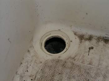 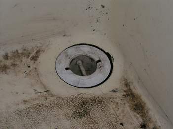 Fig 1, COCKPIT FITTINGS - These are Panache's cockpit drain holes prior to washing and sanitizing with acetone for resealing. The cross pin was installed fore/aft so small debris can slither down the side of the fitting when heeled, back into the drink where it belongs. They were amazingly easy to twist loose in their mounting holes which is the reason they were a major source of water in the locker. This is the first time these fittings were resealed since they were installed at the factory about 30 years ago. It wouldn't hurt to inspect them every 5 years and reseal when required! Sealant lasts about 7 years. These fittings should be installed before the transom fittings as a reference to mark between them. Fig 1, COCKPIT FITTINGS - These are Panache's cockpit drain holes prior to washing and sanitizing with acetone for resealing. The cross pin was installed fore/aft so small debris can slither down the side of the fitting when heeled, back into the drink where it belongs. They were amazingly easy to twist loose in their mounting holes which is the reason they were a major source of water in the locker. This is the first time these fittings were resealed since they were installed at the factory about 30 years ago. It wouldn't hurt to inspect them every 5 years and reseal when required! Sealant lasts about 7 years. These fittings should be installed before the transom fittings as a reference to mark between them.
|
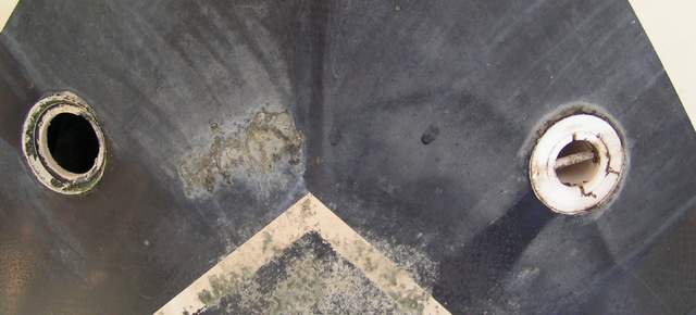 Fig 2, THRU-HULL FITTINGS - These are Panache's two cockpit drain holes as seen from under the hull. This is not a common view of an SJ23 which is why it might look odd. The white pointy line at the bottom is the aft end of the water line. Fig 2, THRU-HULL FITTINGS - These are Panache's two cockpit drain holes as seen from under the hull. This is not a common view of an SJ23 which is why it might look odd. The white pointy line at the bottom is the aft end of the water line. Despite the marine growth under the port fitting, it didn't leak. There was still a thin line of sealant holding the water back, but obviously it was time to reseal it. The clean area below both fittings is caused by the cockpit water dribbling to the lake. Since the boat lays to starboard a bit at the mooring most of the cockpit rain water flowed out here. This is the first time these fittings have been removed since they were installed 30 years ago at the factory.
NOTE: This also an excellent view of what to consider to plug one of these fittings! See what I mean about not being able to use a tapered wood plug because the cross pin blocks the way! In fact a shallow rubber plug might be the best thing to use. Either of these would need a slot cut into it to slide past the cross pin. Come to think of it, it would be very difficult to push a plug in while under water because you have nothing to brace your body against, unless you can push on the rudder with your feet. Hmmmm!
|
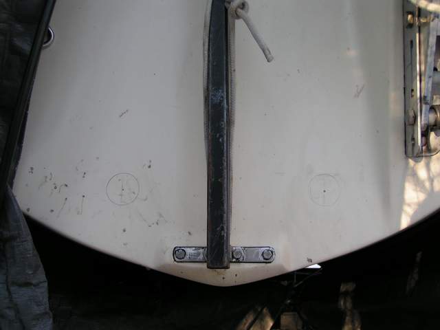 Fig 3, LOCATE THE TRANSOM FITTINGS - Here you see the final two circles I drew on the transom. We drew them in several places till we found the spot that produced the most slope to drain the hoses, where the nuts would also bed against a flat surface and the fittings would be symmetrical on the transom. It seems easy, but it wasn't. Fig 3, LOCATE THE TRANSOM FITTINGS - Here you see the final two circles I drew on the transom. We drew them in several places till we found the spot that produced the most slope to drain the hoses, where the nuts would also bed against a flat surface and the fittings would be symmetrical on the transom. It seems easy, but it wasn't.
My buddy Roy helped me with this job. He saved me a lot of time, not to mention my back, to confirm the location on the outside while I was under the cockpit. This is another one of those jobs where I rediscovered just how agile you have to be for boat maintenance. A second opinion doesn't hurt either!
NOTE: Notice the tiny pin point holes in the center of each circle. I rested the drill bit against the gel coat till they just penetrated the gel coat. This allowed sun light to pass through the fibreglass to the inside making it easy to confirm location. The two dots of light visible from the inside confirmed that we had correct alignment. If they were in the wrong location we could simply drill a new one, ignoring the wrong one. Its always a good idea to maximize your odds.
|
Fig 4, GUDGEON - The bottom gudgeon was resealed during this job. It also confirmed the thickness of the transom. Fresh Sikaflex is extremely sticky. Years later I switched to butyl rubber which sticks better and isn't sticky to my hands.
|
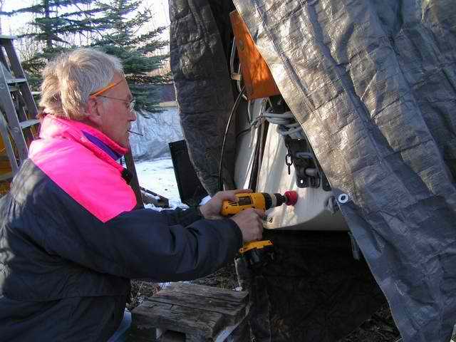 Fig 5, DRILL THE HOLES - Drilling the first hole and there is no turning back now. At least the wind is at my back, blowing the dust away. Boy am I nervous because a screw up here can lead to a major problem. You have to believe your measurements. It pays to be sure of every step before proceeding because then it usually turns out as expected. Fig 5, DRILL THE HOLES - Drilling the first hole and there is no turning back now. At least the wind is at my back, blowing the dust away. Boy am I nervous because a screw up here can lead to a major problem. You have to believe your measurements. It pays to be sure of every step before proceeding because then it usually turns out as expected. Notice that I'm drilling at an angle to the transom so the thru-hull fitting will fit snug in the hole. This is crucial if the fitting is installed horizontally using wedge spacers. If you are installing the fitting flush, then you must drill perpendicular to the transom surface.
I was amazed at how much battery power it took to drill these holes. It helps to set drill to low speed. You just have to go slow and let the hole saw do its work. Fibreglass can be pretty tough on the teeth which is another reason to go slow. In addition, I switched the pilot drill bit to a longer one so it was fully sunk in when the hole saw first touched the hull. This prevents the hole saw from "walking," making a mess of the hole. The original bit is in my mouth so I don't loose it in the snow.
|
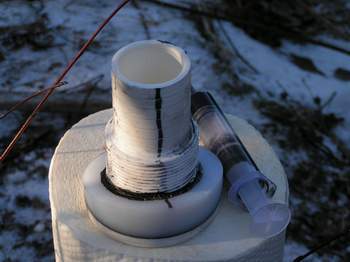 Fig 6, ALIGN THE INSIDE & OUTSIDE WEDGES - This is the line I drew on each fitting to facilitate alignment of the inside wedge to the angle of the thru-hull fitting and mating with the outside wedge. Perfect alignment eliminates torque loading on the fitting, ensuring a long life. Pretty good for on the spot engineering. The technique worked 100% with no guess work or fuss. Fig 6, ALIGN THE INSIDE & OUTSIDE WEDGES - This is the line I drew on each fitting to facilitate alignment of the inside wedge to the angle of the thru-hull fitting and mating with the outside wedge. Perfect alignment eliminates torque loading on the fitting, ensuring a long life. Pretty good for on the spot engineering. The technique worked 100% with no guess work or fuss.
Laying next to the fitting is my DIY "sealant hypodermic". Actually, it is commercially available to inject epoxy. This hypo is equipped with a curved tip that you have to cut off to create the size of bead you need. I use it to inject a neat 1/8" wide bead of Sikaflex in a tight spot. Neat as it may be, this is still no reason to eliminate masking tape. All just in case of a slip and to minimize clean up. When I'm done with the hypo I wash it in acetone with several gushes of the plunger. Sometimes I have to pull a tiny strip of cloth through the tip to remove lodged sealant.
|
|
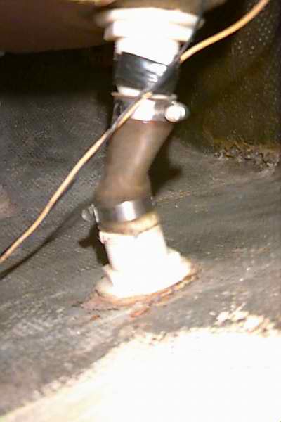
Fig 7, DRY FITTING INSIDE VIEW - This is the view under the cockpit during the dry fitting. There is very little thread showing between the cockpit drain fitting and the new elbow fitting as I cut off all excess thread to screw the elbow to full depth. This achieves the most slope for the drain hose. The final tightening of the elbow fitting is when I pointed it to the transom fitting.
Notice there is no reinforcement at the inside bottom of a Mark I transom as on the Mark II at the top with the black hose.
|
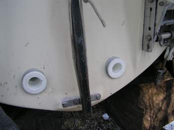 Fig 8, SEAL THE TRANSOM - With the dry fitting now complete we are ready to seal and tighten each fitting. Sanitize the surfaces. We had to work pretty quick as it was cooling off with the setting sun. The Sikaflex should be applied at no lower than 40C. It sure helps to keep the tube at 200C so the stuff can flow. Job done. Fig 8, SEAL THE TRANSOM - With the dry fitting now complete we are ready to seal and tighten each fitting. Sanitize the surfaces. We had to work pretty quick as it was cooling off with the setting sun. The Sikaflex should be applied at no lower than 40C. It sure helps to keep the tube at 200C so the stuff can flow. Job done.
MEASUREMENTS - Just for reference, the fittings are 8" apart and 1 7/8" from the bottom edge of the transom. Each hose is 11.5" long.
|
It was at this point that I relaxed knowing that we had a fix and the hull was sealed. It sure feels good when it all comes together so nice. The fiber reinforced polyurethane tubing was installed a few days later after the Sikaflex cured and the temperature rose to 60C. With the help of a pot of hot water to soften the ends, the tubing slipped right over the barbed fittings without complaint. The hose clamps were tightened after the tubes cooled off. The electrical wiring was secured to its permanent hangers. At long last, good drainage.
|
|
 PLUG THE HOLES THROUGH THE BOTTOM - Of course once you install the transom fittings you must seal the two
holes through the bottom of the hull. It sort of defeats
the purpose of this modification to leave them open! The
Gougeon
Brothers have developed a well documented technique for this type of repair. I
used their version that involves building a stepped
"fibreglass puck" the same size and shape to fit the flange of the
factory thru-hull fitting. The puck was epoxied in the hole and since
the outside face of my puck already has gel coat on it, this eliminates having to apply it later. The plugs I cut out of the transom
were used as the inside stepped up portion of the puck. I formed the layers
to machine fit the hole (for ~1/8" clearance) and epoxied them together. Let cure for a couple of days. Dry fit, roughen the
surface of each hole, sanitize it and apply the epoxy. PLUG THE HOLES THROUGH THE BOTTOM - Of course once you install the transom fittings you must seal the two
holes through the bottom of the hull. It sort of defeats
the purpose of this modification to leave them open! The
Gougeon
Brothers have developed a well documented technique for this type of repair. I
used their version that involves building a stepped
"fibreglass puck" the same size and shape to fit the flange of the
factory thru-hull fitting. The puck was epoxied in the hole and since
the outside face of my puck already has gel coat on it, this eliminates having to apply it later. The plugs I cut out of the transom
were used as the inside stepped up portion of the puck. I formed the layers
to machine fit the hole (for ~1/8" clearance) and epoxied them together. Let cure for a couple of days. Dry fit, roughen the
surface of each hole, sanitize it and apply the epoxy.
In the Gougeon technique they recommend wetting all surfaces
with unthickened epoxy, let soak a minute, then wet with thickened epoxy. Twist the puck into the hole and temporarily hold it in place with a plastic
covered stick across the back of the hole. Drive a short screw through the
stick into the back of the puck. Wipe off the epoxy that will ooze out
around the puck. Ensure that the puck is fully saturated with wet epoxy at
the perimeter as you must have 100% coating/adhesion around the puck
for maximum strength and sealing. Once the epoxy has cured to the green
stage it is safe to remove the stick as it is time to apply the inside layers. Apply
several successive smaller layers of cloth saturated with epoxy on the
inside of the hull. Make the bottom layer of cloth (largest) about 5" in
diameter. These layers of cloth effectively clamp the puck in place. Five
layers should suffice. Smooth the outside of the puck flush to the hull with thickened
epoxy and apply bottom paint.
PS: The reason for laying the larger diameter cloth down
first is so you can squeeze the air bubbles out of each subsequent smaller layer. If the larger cloth is on top, it would encapsulate the bubbles
reducing the ultimate strength.
 Since
Panache was parked in the bush for the winter and I don't have access to
commercial AC power for heat, I had to wait till a warm Spring day for the temperature to hit
200C.
This is rare on the Canadian prairies. I used an underwater repair
epoxy with the consistency of putty to stick the puck to the hull without mechanical support from the inside. This allowed me to do this job on my own. After mixing the A
& B components I smeared it on the inside of the puck, covering all
the surface. Then I twisted the puck in the hole till the epoxy oozed out,
inside and outside. This was more difficult to do than I
thought because it required a lot of force to ooze the slow
flowing putty around the edge of the puck. I had to lay on my back
and push and twist the puck in with my boot, with a
sheet of paper over the puck to keep it clean. In hindsight an epoxy with
the consistency of a paste might have been an easier job. However, once the puck sunk to
full depth I scraped the excess epoxy off with a putty knife and smoothed
the gap with finger tips. The epoxy that oozed out on the inside was also
scraped smooth, being careful not to push the puck back out. Then I let the
whole works harden for an hour till the epoxy cured. Shortly afterwards I sealed
the inside with a layer of thickened epoxy as shown in the diagram above. This
last application capped and locked the puck in place. Later I smoothed the outside of the
puck flush to the hull with epoxy and applied a coat of bottom paint. Since
Panache was parked in the bush for the winter and I don't have access to
commercial AC power for heat, I had to wait till a warm Spring day for the temperature to hit
200C.
This is rare on the Canadian prairies. I used an underwater repair
epoxy with the consistency of putty to stick the puck to the hull without mechanical support from the inside. This allowed me to do this job on my own. After mixing the A
& B components I smeared it on the inside of the puck, covering all
the surface. Then I twisted the puck in the hole till the epoxy oozed out,
inside and outside. This was more difficult to do than I
thought because it required a lot of force to ooze the slow
flowing putty around the edge of the puck. I had to lay on my back
and push and twist the puck in with my boot, with a
sheet of paper over the puck to keep it clean. In hindsight an epoxy with
the consistency of a paste might have been an easier job. However, once the puck sunk to
full depth I scraped the excess epoxy off with a putty knife and smoothed
the gap with finger tips. The epoxy that oozed out on the inside was also
scraped smooth, being careful not to push the puck back out. Then I let the
whole works harden for an hour till the epoxy cured. Shortly afterwards I sealed
the inside with a layer of thickened epoxy as shown in the diagram above. This
last application capped and locked the puck in place. Later I smoothed the outside of the
puck flush to the hull with epoxy and applied a coat of bottom paint.
It is important that you follow the epoxy application instructions
exactly. Preparation is everything. Get real religious about this. Inspect your work in each step. A good repair is
the same colour as the rest of the hull (inside view) and the edges of all
layers of cloth are fully encapsulated. Once cured the puck will withstand
blows from a rubber hammer, something you should do to confirm the integrity
of your work. If you don't trust your repair work then find
someone else to do the work for you. A bad repair will find your boat at the
bottom of the drink.
Launch the boat and check for leaks. Kinda
keep an eye on the water line for awhile! If all of it
stays visible, THEN go drink your beer to celebrate!
|
|
THRU-HULL FITTING MAINTENANCE
There are zillions of boats that have sunk due to neglected
maintenance. Fact is, it's
actually quite easy to stop a boat from floating! You don’t have to do anything. Just let your boat sit
a few years and eventually it will find the bottom all on its own! According to
statistics for every boat that sinks at sea, four go down in their slips,
all for lack of maintenance. Pretty alarming isn't it?
So if you don't
want to change the cockpit drain design then at least inspect the fittings,
sealant, hoses and clamps for overall integrity. As a word of caution, a Delrin
or plastic thru-hull fitting will become brittle with age so this is another good reason to
inspect them on a regular basis and replace a weak one before it breaks.
If you question the soundness of a fitting, give it a good rap with a (2x4)". Better they break on the
trailer than five miles from land. That could be a real, "Oh
damn" situation. In the same line of thinking, replace any hard polyurethane hose. You can test the integrity of the sealant by spinning the nut loose and
wrenching or twisting the fitting from the inside. If there is any
indication that the sealant is loose, redo it. The factory
polysulfide sealant has hardened by now and creates a
marginal
seal. Don't be surprised if you find it crumbly when you remove the
fitting. This is a sure sign that it should have been resealed years ago. While
today's superior sealants work better and stay pliable longer, they have
a definitive lifetime as well! So don't be lulled into complacency. Read the warning below about freezing weather.
To disassemble,
loosen the nut and the hose clamps on the cockpit
fitting, crack the sealant and lift it up out of the cockpit sole along with the hose. A difficult to release hose can be removed easier with a hose removal tool. You can generally remove the hose without damaging the barbs that a knife cut will. Clean all components and reinstall in the
reverse order. Seal all fittings to the hull with Sikaflex. Replace the old hose with new clear polyurethane high pressure fiber
reinforced hose. A new polyurethane hose
can be persuaded to slip over a barbed fitting if you first soak the
hose end in very hot water. This will make the polyurethane pliable, permitting a
full depth fit over the barbs. Let the hose cool before you tighten the hose
clamps. Tighten the clamps till the hose material just starts to swell out the holes, NOT any further. Some
of it should ooze out all around to ensure a water tight seal. If
you want to test the seals for water
tightness, seal the bottom fitting with a rubber plug and fill
the tube with water. Watch for several days!
_____________________
SAFETY
NOTES ABOUT THRU-HULL FITTINGS ____________________
-
FREEZING WEATHER
- Drain these tubes during haul out by stopping on the sloped ramp. I park Panache with the bow up in winter so water can run along the decks to the scuppers or the cockpit drains through the tubes. Failure to do so can lead to a split elbow, a cracked drain tube or a split thru-hull fittings as the ice expands inside. Once the drain seal is compromised, subsequent water will flow from the cockpit to fill the hull under the cockpit. Now that's a disaster. This is why it is so important to cover the boat when stored in freezing weather. If the drain tubes on your boat slope up to the transom, suck the water out with a pump and consider shoving in a down turned fitting for winter to keep the water out.
-
PROTECT THE PLUMBING
- Don't store your "cruising gear" around the drain hoses under the cockpit. It should go without saying that heavy articles shouldn't push against the fittings or hoses. I
know of several boats that have had a close call due to a heavy article that
dislodged a drain hose in a bouncy seaway. If you enjoy the adrenalin
rush of plugging holes and racing to shallow water then go ahead, store
your heavy items here! The inside of the hull is quite
smooth so they will slide easily!
-
WOOD PLUG - If you want to use a tapered wood
plug to block the water flow at a fitting, then consider removing the cross pin
in each thru-hull fitting. Use a very fine tooth saw and be gentle with
the action as the pins are not part
of the original casting. They are actually inserted across the fitting and
glued in place. I think the purpose of this pin is to prevent
'babies" and other small objects from sliding into the "drink!"
The pin will just
as easily
stop a long wood plug, rendering this technique useless.
- The barbed end of a fitting is 1 1/8" ID, the flange end of a
fitting is 1 3/8" ID and the hole through the hull is 1 7/8"
ID. So
if you use a tapered plug select one that is slightly outside these dimensions,
1" to 2". This size will protect you from a hose that has
fallen off to a fitting that is no longer attached to the hull. The latter is
unlikely to happen unless you drive the plug too far into the barbed end
of a fitting, splitting it. Damn!
- Tie the wood plug close to the fitting where you expect to use
it so you
don't have to go searching when trouble arises. Make the cord long enough to reach either the cockpit or the
transom fittings.
-
KITCHEN SINK PLUG - You could also use a tapered soft rubber plug, (similar to a kitchen
sink plug). They seal quite well and are usually
short enough that they DON'T bottom out against the pin. Make them black
to withstand UV better and so you can
see them to restore drainage.
-
STA-PLUG EMERGENCY PLUG - A soft ribbed cone shaped plug made of high density
foam that conforms to any shaped hole to create a water tight fit.
For example; Tearing the cone at the eights rib will create a plug with a 2" diameter
base that you can jam into a thru-hull
fitting. If unused it remains soft for many years and will not mould,
split or swell
like a wood plug.
SPLISH SPLASH - Regardless of the style of plug,
the foam version comes in real handy should you want to take a bath in the cockpit!
Just
remember to remove them after your bath! The first good rain fall
may find your baby sitting real low in the drink.
-
CONSIDERATION for UV ROT (HOSE) -
If the inside of your vinyl drain hoses have been exposed to the sun for many
years, it would be wise to inspect them. They can harden, rot, and
break, leading to an inconvenient sinking when waves splash against the transom.
Remember, there is double exposure of UV from the sun and the water. A black
automotive hose (shown above) might actually be better suited for this application.
-
CONSIDERATION for UV ROT (THRU-HULL FITTING) - A cracked nylon thru-hull fitting is actually quite common. It can't stand up
compared to bronze or Marelon. UV deteriorates nylon quicker with
age. Some fail within a year. In addition, the stress of an
unsupported hose can break a weak fitting, with the weight acting as a lever
as the boat bounces. The failure typically occurs
where the body of the fitting meets the outer flange. Once the
body falls off there is nothing left to
keep the water out.
NOTE
- The tapered UHMW spacers I installed in 2004 (shown
above) are starting to show UV
fatigue. Therefore I'm looking for a replacement material.
In the mean time I covered them with electrical tape to block the UV
and monitoring their status. All is OK so far.
|
|
FLOATATION: Just in case you are thinking
of adding floatation to a 3000 lb. SJ23, it requires approximately 50 ft3
of air to hold the hull at the surface. Actually it is a bit less than that
but the extra buoyancy is helpful to support crew and cruising junk onboard.
Be careful about assuming the boat weighs only 3000 lbs. Many come in
higher than 3000 lbs. due to the skill of the guys at lay up time. Confirm
the weight on a
commercial truck scale. If you can split the floatation 50/50 between the
bow and stern and there is sufficient volume to install it then the boat
should float level, more or less. You could use air bladders or rigid foam.
There are problems with either of these, mainly access to the respective
bilges. One person suggested installing deflated air bags connected to a CO2
bottle. In the event that a sinking occurs open the valve and your
floatation is ready to assist you. It would be wise to test the bags on a regular
basis.
In practice though, a fibreglass hull rarely breaks to cause a sinking.
It is generally a thru-hull fitting or a hose that fails or a grounding
on rocks that grinds the material. Most
hulls can withstand quite an impact before they crack to cause a sinking.
Swamping the cockpit is probably a more common occurrence. This is why you should
sail with the hatch and companionway shut in rough weather. Many people will
drag an inflatable behind the boat. They have excellent floatation and stability.
If you absolutely have to be out there, then it is wise idea to wear a cold weather immersion suit,
plus a life jacket
or an inflatable PFD. Also, leave your float plan with somebody AND STICK TO IT. Regular position reports via the VHF wouldn't hurt
either. One would think that waiting it out in the restaurant or in a quiet
harbour would be the better part of valour. Better this than to make a
nuisance of yourself with Search and Rescue!
|
|
Return
to Tech Tip Index. . . . . . . . . . . . . . . Have
a Question? |