| SJ23 Tech Tip D04, (Updated 2024-03-16) Frank May, Bob Schimmel | |
|
Outboard Mounting Bracket - Rework the Fulton Bracket to Stiffen it. |
|
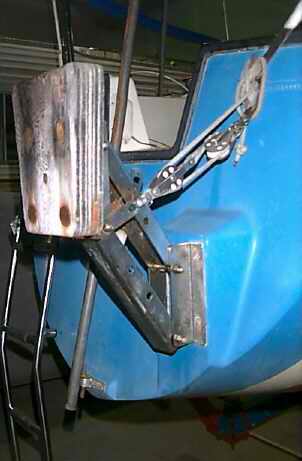
The San Juan 23 was factory equipped with a Fulton
MB1410 adjustable outboard bracket. While this bracket has hung on
Panache's transom since manufacture (30 years at time of this Tech Tip), I babied it for the past 10 years. In my opinion it is over rated for a 20 HP (2 stroke) or
5 HP (4 stroke) long shaft outboard. The bracket may perform OK pushing a planning hull
on a mill pond, but it is under rated for a pocket cruiser operating
in the heavy pitch and yaw loads imposed by steep 4' waves.
You can find these waves on a shallow lake, at a harbour entrance or where wind
and current oppose each other. A steep wave can present some very significant forces. On two
occasions I was unable to
raise the bracket, the motion was that violent. What surprised me is how much the bracket swayed
sideways. So
much so, that I thought it was close to
bending. 4" of sideways movement on a 14" pivot arm is far too much for my
liking. Both times I was tempted to tie a line around the outboard to
steady it, but judged the risk of falling overboard too great, along with
the fact that I just might
 need to use the outboard. The flexing gave me quite a concern, just when I needed to concentrate on boat handling. A Mercury 7.5HP equipped with electric
start or a Honda 8HP each weigh ~65
pounds. The Mercury was a popular outboard in the mid 1970s and the Honda ~10 years later. To answer
the obvious question of why I'm not sailing in winds that strong? Well
usually I do, but sometimes an SJ23 needs some extra punch
from the outboard to maintain headway in steep waves. A shoal draft keel has its limitations and adding propeller push is sometimes necessary for a flatter bottomed hull.
Not so
in a deep keel wine glass shaped hull. It is prudent to be in a safe place prior to the storm, but sometimes the hull requires an extra push from a
dependable outboard mounted on a stable bracket. need to use the outboard. The flexing gave me quite a concern, just when I needed to concentrate on boat handling. A Mercury 7.5HP equipped with electric
start or a Honda 8HP each weigh ~65
pounds. The Mercury was a popular outboard in the mid 1970s and the Honda ~10 years later. To answer
the obvious question of why I'm not sailing in winds that strong? Well
usually I do, but sometimes an SJ23 needs some extra punch
from the outboard to maintain headway in steep waves. A shoal draft keel has its limitations and adding propeller push is sometimes necessary for a flatter bottomed hull.
Not so
in a deep keel wine glass shaped hull. It is prudent to be in a safe place prior to the storm, but sometimes the hull requires an extra push from a
dependable outboard mounted on a stable bracket. The
locking feature of the lifting arm was the first component to fail and I stopped
using it because it would release occasionally. Since I use a 4:1 block and tackle to
raise or lower the outboard, I tie the bracket in the 'up' position to
prevent it from dropping. "I bloody near go through the roof when
the lever lets go
in the middle of the night as the outboard drops with a thunk. The
sound reverberates through the entire hull, which is particularly annoying
when you are in the dream state!"
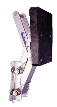
SALT WATER BRACKET (2004) - Many current salt water rated outboard brackets are more robust and rated for a higher horse power. They are also equipped with an internal gas spring that provide lift which makes them an attractive upgrade for a silver haired sailor! Present company excepted! The OMC outboard bracket (shown below) is an example of such a unit. It is rated for up to15 HP and has an internal gas spring that makes raising or lowering a 'piece of cake.' The pivot arms are spaced far apart to eliminate sideways movement. Unfortunately, if you don't replace like for like, the mounting bolt holes of the new wider brackets don't line up to the original holes on an SJ23. The narrow outboard mounting "pod" on the transom of an SJ23 makes upgrading to the new wider outboard bracket difficult. The SJ23 pod was sized for the narrow foot of the original style Fulton bracket. The foot print of all the current brackets are much larger. It should be noted that Fulton MB1820 now has a good design (shown at right) for a pocket cruising sailboat. It is quite an improvement over the early design shown above in that it is more rigid and has all stainless steel parts. I think this is an early design of the MB1810 saltwater bracket that is rated up to 30 HP 2-stroke or 6 HP 4-stroke, max 130 lbs. The 3" wide formed pivot arms are effective at eliminating sideways play and the mounting plates line up to the mounting holes through the SJ23 transom pod. This improved design is what prompted me to stiffen Panache's bracket. Another good stainless bracket with no sideways movement is the Garelick model 71056. However, it requires an adapter plate to mount on an SJ23.
|
|
|
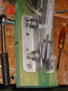
TRANSITION PLATE to MOUNT LARGER BRACKET - Frank May. NOTE -
"I got this excellent bracket at such a good deal that I didn't want to
pass it up. Therefore I designed this transition plate to mount it using
the original pod holes." |
|
 CONSTRUCTION - One solution to the bolt hole
alignment problem is to fabricate an external transition plate from 1/4"
aluminum. Frank May did this to "Jafeica" in the Spring of 1998 when he purchased
a used bracket. CONSTRUCTION - One solution to the bolt hole
alignment problem is to fabricate an external transition plate from 1/4"
aluminum. Frank May did this to "Jafeica" in the Spring of 1998 when he purchased
a used bracket. "Cut the aluminum plate to size then shape and pre-drill the holes before final assembly. The edge of the plate must be ground smooth with a hand grinder. I also recommend installing the plate to the boat first, then the bracket to the plate. Use a piece of solid hard wood and large stainless steel washers against the inside of the hull. Install the bolts with the heads on the inside and the nuts on the outside. This facilitates checking the nuts for tightness in the future. I was a little afraid that the plate might look ugly, but once it's on you don't even notice it. I also replaced all the worn pins with stainless steel for the extra security. Whatever you decide to do, bolting through the hull is a real lousy job that is described in Tech Tip D03 . At left is an image of my transition plate." Frank May.
This
is Mike Forman's experience with a similar installation and a twist to
the rudder solution.
Always
use a marine sealant
or adhesive between the metal plate and the transom to seal the bolt
holes and to prevent movement and marine growth between.
|
|
|
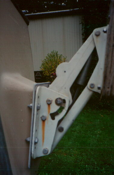
When I modified Panache's Fulton MB1410 bracket as described below, I
experienced the same rudder overlap that Mike had. I solved it by
adjusting the limiting the height
of the bracket in the down position (bottom limit of travel) and
installed a taller outboard mounting block so the outboard rests about an inch
higher. Thankfully this was possible on my modified bracket but is is seldom possible on a retail bracket. It is
difficult to determine which outboard bracket will be suitable on an SJ23
as there are many combinations of brackets and outboard sizes. One
method would be to clamp the outboard on the bracket and hold it up against
the mounting pod. Then swing the rudder to determine if you have
clearance. Do this with the bracket in the up and down positions.
Here's hoping you find some muscle bound guy to help you with the outboard! This is
not an easy job. |
|
|
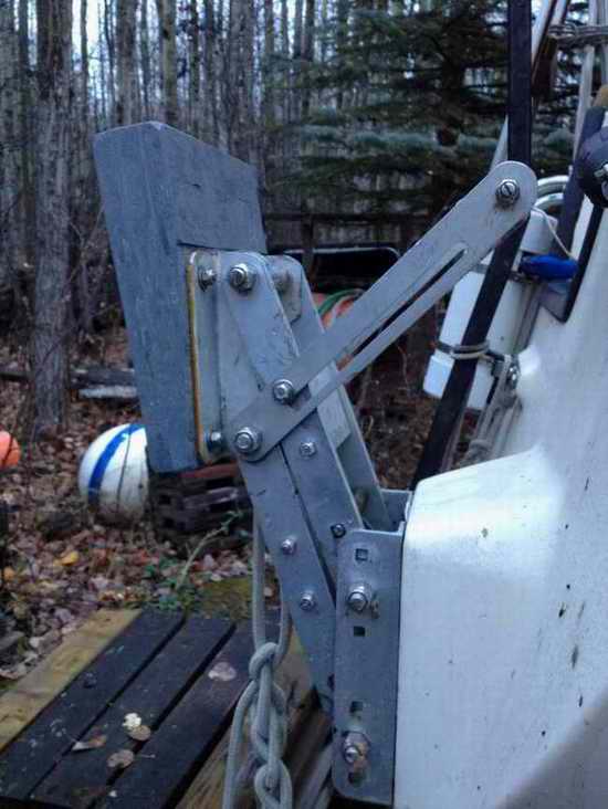
STIFFEN the ORIGINAL FULTON MB1410 BRACKET (2006) NOTE
- "I modified Panache's original Fulton
MB1410
bracket, shown at the top, to eliminate the side flex. A friend suggested this idea 4 years earlier when he watched my outboard flexing sideways while sailing next to me. I took his suggestion and added a bit
of
ingenuity to design a workable modification that also looked good.
I wouldn't normally go through all this work except that I wanted to use
the same bolt holes on Panache's mounting pod. I don't have access to a
retail outlet of outboard brackets in oil country here. But I did incorporate some design
features of other brackets I've seen." Blatant plagiarism. Bob Schimmel |
|
 Modifying
the Fulton
MB1410 adjustable outboard bracket may have been time consuming but it was pleasurable
work. To justify this project I balanced the amount of work versus the cost of a replacement
unit. "The fact that a beer was on the table against a successful modification had nothing to do with it but it sure tasted good!" I chose to modify this
bracket since
a replacement unit that fits the transom pod is not available.
The modified
bracket had to be stronger and safer than the original design or there was
no point in changing it. It should also look good and still fit to the outboard pod on the transom. When you consider how much force this bracket
has to hold, without failing,
all aspects of the redesign had to be considered. Modifying
the Fulton
MB1410 adjustable outboard bracket may have been time consuming but it was pleasurable
work. To justify this project I balanced the amount of work versus the cost of a replacement
unit. "The fact that a beer was on the table against a successful modification had nothing to do with it but it sure tasted good!" I chose to modify this
bracket since
a replacement unit that fits the transom pod is not available.
The modified
bracket had to be stronger and safer than the original design or there was
no point in changing it. It should also look good and still fit to the outboard pod on the transom. When you consider how much force this bracket
has to hold, without failing,
all aspects of the redesign had to be considered. My thought was to interchange the pod mounted angle brackets (left to right) thereby spreading the pivot arms, add a few judiciously placed spacers between the pivot arms to stiffen them, plus some other clever tricks, to achieve the required sideways rigidity. The final design would look similar to the Fulton MB1810 deep water bracket shown at left. Naturally I reused a lot of the original parts, otherwise there would be no challenge in this project! However, at some point in this conversion I realized there was no going back to the original design, so assess your conversion and work carefully. CONSTRUCTION - All parts are stainless steel or aluminum.
PAINTING - If you decide to paint the aluminum components, wash them first with a mild acid to remove any grease, then sanitize with acetone and finally prime the surface with a coat of zinc chromate. Zinc chromate is nasty stuff to breathe so paint outside in a mild wind (nobody downwind) and wear a mask. Flat black paint matches the toe rails but the aluminum will get very hot in the sun. I abandoned this idea, thinking that the paint will likely bung up the hinges. Anodizing them in black would have looked nice but I wanted to go sailing. The aluminum has since acquired a very acceptable patina from exposure to the lake water and it blocks further oxidation. MOUNTING
- Once
you are satisfied that the bracket works, mount it on the transom using Sikaflex or butyl rubber between the hull and the
angle mounting plates
to seal the holes and prevent marine growth. Use nylon lock nuts
inside the hull backed up with large SS washers against a sealed hardwood block. If you measured
correctly, your modified bracket will fit perfectly
over the old mounting holes.
PARTS LIST
FIELD EXPERIENCE
HINT
- Here is a tip to ease outboard installation on the bracket,
assuming you are on the launching ramp with
the boat on the trailer. You aren't getting any
younger and don't let your ego get in the way to wreck your back! Tie a ~10' long line in a loop secured to the
bottom of the bracket and pull the bracket down to the bottom of its
travel. Place your foot on the loop of line to hold the bracket down.
Now lift the outboard up onto the
bracket (keep your back straight) and tighten the locking handles. This is much easier than fighting the lift springs.
You're not going to win that battle. Reverse the procedure to remove the outboard. Holding the bracket down prevents the springs from following the outboard when
you lift it up! Clever huh?
|
|
|
Return to Tech Tip Index. . . . . . . . . . . . . . . Have a Question? |
|
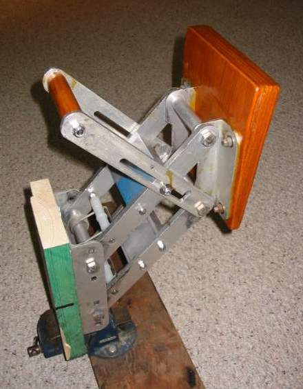 PIVOT
ARMS - The upper and lower pivot arms rotate on four 6" long x 1/2" SS bolts. There is also a 4" aluminum compression tube over each bolt. Sections cut from an old ski pole work just fine for this. The 4"
compression tubes
must fit tight between the pivot
arms to keep them apart. You can see the upper tube between the pad braces in the photo at right.
PIVOT
ARMS - The upper and lower pivot arms rotate on four 6" long x 1/2" SS bolts. There is also a 4" aluminum compression tube over each bolt. Sections cut from an old ski pole work just fine for this. The 4"
compression tubes
must fit tight between the pivot
arms to keep them apart. You can see the upper tube between the pad braces in the photo at right.