| SJ23 Tech Tip H07, (Updated 2024-03-09) Bob Schimmel, Gene Adams, Glen Moore. | |
|
SJ23 Hull Construction and Factory Assembly. |
|
| Some members have asked where to place a bilge pump in a SJ23 and others
have concerns about water freezing between the hull and the hull liner during winter
storage. In a discussion with Gene Adams (Port Gardener Sailboats) and Glen Moore (Clark Boat Company),
I learned some very interesting information. You should know that Gene was
the "last 20' of the assembly line". He corrected any flaws in
a hull that was tagged with a defect. Glen worked inside at various jobs.
|
|
| HOW IS THE KEEL ATTACHED TO THE
HULL - While the keel (ballast) on certain San Juan models is bolted
to the outside of the hull, the ballast of the shoal draft
SJ23 is encapsulated inside the keel stub that is part of the hull. The ballast of the
first production hulls consists of
lead shot (pellets) mixed with resin poured into the keel stub.
Bonding the ballast to the hull ensures it stays in place when a boat
broaches. In later hulls (don't know the serial number) lead castings were placed in the keel stub and similarly
held in place with thickened resin. With either technique
(especially lead shot) it is difficult to control the exact position or
the density of the ballast as is possible with a bolt on keel. On
the other hand there are no keel bolts to corrode or leak and the stub creates a
water tight seal around the ballast, provided you don't crack the
fibreglass by running into a rock or thump the hull down on something hard. Compromises
again! To compensate for a slight imbalance in
the fore/aft position of the ballast, Clark equipped the SJ23 with a fore/aft adjustable
center board. In practice though, the position of the center board has
more to do with balancing the center of lateral resistance with respect
to the center of lateral force. The factory placed the board in the center hole. On some SJ23s the ballast sits so low inside the keel stub that it leaves an air gap above the ballast, between it and the hull liner. This is great for sailing performance but this gap could be filled to prevent water entrapment. Water inside this void is definitely not a good thing in a freezing climate. One symptom of an air gap is a stress crack around the center board lift cable attachment on the cabin sole. To test for an air gap, gently tap on the floor above the keel area. If you hear a hollow sound, you have an air gap. The fact that it sounds hollow is the indication that it is dry down there, which is good. A test could be made to determine the size and depth of the void. On Panache I drilled a 3/8" hole through the floor, just behind the pedestal, and poked a stick down till it bottomed out. I filled the void with cold cure epoxy poured through a tiny funnel. The void required 1/2 litre of resin to fill. It should go without saying that if the void is filled with water, it must be pumped out and dried before pouring in the resin. Another thought on this void. BALLAST - In the original hulls the ballast consisted of lead shot mixed with thickened resin poured into the keel stub adjacent to the center board trunk. In subsequent hulls the ballast consisted of lead castings placed in the keel stub with thickened resin poured in to prevent movement. HOW IS THE HULL LINER ATTACHED TO THE HULL - After the keel is cured (and cooled) in the manufacturing process, a thick layer of mush (lightly catalyzed putty called Q-cell) is sprayed inside the hull, covering the entire area where the liner will rest. Then the liner is lowered in place and a vacuum pump attached over the liner so air pressure compresses the liner uniformly to the hull. Any excess mush is squeezed out along the edge of the liner. The fact that it squeezed out is verification that the liner is bonded completely, ensuring maximum strength. The vacuum is maintained for 24 hours till the whole works solidifies to a cured state. If done correctly, all voids are eliminated, creating an extremely strong hull to liner bond. If you look inside the cockpit lockers, near the front, you might see some of the cured mush that oozed out. Oozed out mush is quite weak on its own and can easily break off. Mush that adheres between two rigid layers creates a very strong sandwich. (Gene Adams says the mush consists of resin and fibre filler mixed to the consistency of mayonnaise).
REMOVE
WATER BELOW THE HULL LINER -
It's a fact of life that eventually water will get inside the hull from
leaks, condensation, spills or pulling the knot meter impellor while the boat is
floating. A popular location for the impellor is below the head,
just forward of
the keel. While the impellor performs best here, a
LOT of water will flow inside the hull under the liner from where it is difficult
to remove.
This is the reason why I no longer remove the impeller with Panache floating. On Panache I enlarged the hole through the floor below the head so my arm
can just reach aft to the edge of the mush by the compression post. This
allows me to soak up most of the water with a sponge.
"If you are concerned
about water freezing between the mush and the hull, a possible solution
is to drill a 3/4" diameter hole through the floor liner, just forward
of the table pedestal. This is the lowest point on the curved
floor and is directly above the ballast. Drill very carefully,
about 3" deep, stopping at the top of the ballast. DO NOT drill
into the cured resin that seals the top of the ballast."
Gene Adams.
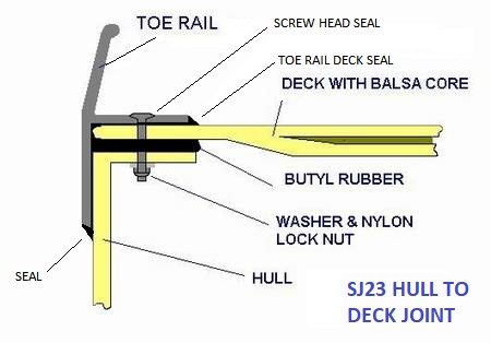
NOTE: The toe rail and hull to deck joint and seal is shown at right. However, the picture shows my improved and stronger bolting technique of aluminum washers and nylock nuts, not using the factory original speed nuts. See Tech Tip B26. DECK CONSTRUCTION - The deck is a sandwich construction using 1/4" plywood in the core to save weight. The majority of the cabin top is balsa core except under the mast step. Solid fibreglass is used to reinforce the deck where a stanchion or winch would be mounted. You will find plywood under the aft part of the deck as well. Plywood was the material of choice at the time to create compression strength and save weight.
HULL WEIGHT -
"The design weight of a San Juan 23 is just under ~2700 pounds. The cabin and the interior pan were made with a chopper gun that sprays resin and fibreglass. It is difficult to maintain a uniform thickness with a chopper gun unless you have the touch of Rembrandt. If you have such a touch you do not need to build boats! The result is that boats varied widely in weight. The extreme was the last boat I worked on, which weighed 4000 pounds, empty. This was 1000 pounds over weight, which is one of the reasons why the people who built it did not stay in business long. As a dealer I got to install the second axle on the trailer. The ~2700 pound design weight is right at the upper edge of what a single axle trailer can support. If your boat happens to be slightly heavier, you need two axles." Gene Adams. |
|
HULL ASSEMBLY at FACTORY
-
"Regarding the assembly of the
SJ23 hull. There are five major sections; the hull, the centerboard trunk, the ballast, the
interior
pan, and the deck that together make the shiny finished fibreglass boat you see.
Anyway... this description should be corroborated with the construction manual." Glen. BULKHEADS - I presume the bulkheads and teak trim was installed in a completed hull. Bob. ------------------------------------ SJ23 CONSTRUCTION MANUAL ---------------------------------------- To Bob: "An SJ23 construction manual would be very helpful if I could find one. I have some change drawings, but no complete manual. There must have been something in the shop, but I have never seen one. I talked to the people in the shop but they never gave me one. A great deal of knowledge about how to build these boats was in their heads. I am starting to put together a manual to pull as much information out of my head and get it on paper. When I have a finished manual I would be happy to share it with you. You have done a great job of documenting details of the boats and you have answers I don't have." Gene Adams.
PS: I never received this manual from
Gene prior to his retirement. I show you this dialogue to demonstrate the processes during
the 1970s and how difficult it is to get accurate answers when
documentation was a low priority.
|
|
|
Return to Tech Tip Index. . . . . . . . . . . . . . . Have a Question? |
|