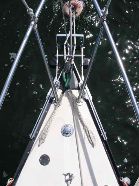
| An anchor roller is one of those really useful "toys"
to have for cruising on a SJ23, especially for all those early manufactured
hulls that were not equipped with the factory
deck anchor locker to conveniently store the "hook and line". Even if your boat is equipped
with the deck locker it still makes sense to add a roller if for no other
reason than to ease the job of retrieving 100' of slippery, slimy line
with chain. The problem with installing a one piece
anchor roller as shown in the marine catalogues, is that the factory bow
cap of an SJ23 is too soft to support one. It could collapse under
the load. However, the style of anchor roller discussed in this Tech Tip will work
on any San Juan and it's best suited for a Bruce or plough style anchor. Best of all, this design
shouldn't interfere with trailer launching but this is a judgment you will
have to make yourself as there are too many variances in trailer designs. The
installation of this roller MUST be done in conjunction with reinforcing
the toe rail and maybe moving the mooring
chocks. While you're at it, you could add a metal bow
cap or relocate your running lights. This may
sound like a lot of work but, if done together it can save a lot of time
and effort by having to the tear the bow apart only once. The bonus is that the bow area becomes water tight for
ploughing
into waves, functional for anchoring and the boat should become
significantly more visible at night. DESIGN CRITERIA - The frame work
and the fasteners for this design must be extremely strong to withstand
the loads of riding to the anchor during a gale force wind. Consider a
typical scenario of snagging your anchor on the bottom. The first thing
that most "deck apes" will do is pull the anchor line in as
tight as it will go, even to the point of pulling the bow down into the
water a bit. Then they walk back to the cockpit singing, "this is gonna to do it." When one of them guns the engine, the loading on the
bow can instantly equal the weight of the hull. The toe rail may be
strong but it's not designed to handle this type of load.
This is exactly why the compression strut is so crucial and why the toe
rail fasteners must be beefed up. Now just for the fun of it the frame
must also be capable of holding your body weight, because at some point in
time you will stand on it. However, your weight is peanuts
compared to anchoring in a storm. And let's not forget the missed
turn in the harbour when you jam the bow into a piling. Ouch! It
would be real embarrassing to bend your brand new anchor roller, never
mind the pulpit. In short, the frame must never fail, the hull
should fail first. If you follow all the guidelines it will be strong
enough.
Once you understand the concept of this design there are
many variations you can adopt to suite your own requirement. I know
of four variations and they all work just fine. However, as tempting as it may
seem, the one variation I don't suggest is a single roller. The anchor
line will chafe on the sides of the stem head fitting and the forestay when they are so
close. Still, if you insist on a single roller, I'm sure there's a way of
working around these problems. Let me know how you make out with your
design. I would like to hear about it.
|
 1 -
STRENGTHEN the TOE RAIL MOUNTING - (This is the
first job you MUST tackle as there is no point in fastening a strong
roller to a weak mounted toe rail). At the very least you MUST reinforce the toe
rail from the bow back to the forward bulkhead, then complete the
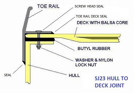
remainder at a later time. The hull to deck joint consists of two
flanges that are sealed and bolted together along the gunwale. The top of the hull flange
is sealed to the underside of the deck with a continuous bead of butyl rubber.
It is mechanically
fastened with machine screws through the toe rail and hull flanges every 6". The toe rail adds a
tremendous amount of reinforcement to this joint. The hull flange is
actually an extension of the top of the hull, turned inwards to create a
lip that the deck rests on. It is quite substantial, having a minimum thickness of 1/8".
The port and starboard hull flanges extend across the top of the transom,
including the
bottom of the transom notch. There is no flange along the sloped
sides of the transom notch. There are no bolts through
the transom flanges. During the hull assembly a wide bead of butyl rubber is applied on top of the
hull flange and when the deck is lowered on the hull it seals the flange.
A few pop
rivets are judiciously set in place to lock the alignment of the deck to
the hull for later attaching the toe rail. Finally the toe rail is bolted on, starting at the
stern, ending at the bow. 1 -
STRENGTHEN the TOE RAIL MOUNTING - (This is the
first job you MUST tackle as there is no point in fastening a strong
roller to a weak mounted toe rail). At the very least you MUST reinforce the toe
rail from the bow back to the forward bulkhead, then complete the
remainder at a later time. The hull to deck joint consists of two
flanges that are sealed and bolted together along the gunwale. The top of the hull flange
is sealed to the underside of the deck with a continuous bead of butyl rubber.
It is mechanically
fastened with machine screws through the toe rail and hull flanges every 6". The toe rail adds a
tremendous amount of reinforcement to this joint. The hull flange is
actually an extension of the top of the hull, turned inwards to create a
lip that the deck rests on. It is quite substantial, having a minimum thickness of 1/8".
The port and starboard hull flanges extend across the top of the transom,
including the
bottom of the transom notch. There is no flange along the sloped
sides of the transom notch. There are no bolts through
the transom flanges. During the hull assembly a wide bead of butyl rubber is applied on top of the
hull flange and when the deck is lowered on the hull it seals the flange.
A few pop
rivets are judiciously set in place to lock the alignment of the deck to
the hull for later attaching the toe rail. Finally the toe rail is bolted on, starting at the
stern, ending at the bow.
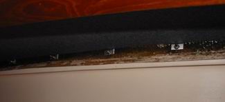
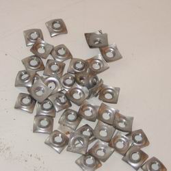 The two toe rails are bolted with ninety
two #8 size Roberts pan head
machine screws (10/24 thread, 1.5" long) with 3/8" square cupped threaded
nuts as shown at left. The corners of these nuts bite into the bottom of the
fibreglass hull flange
where they can't turn so they can be tightened by one person from above. This
may save time during assembly but these small nuts concentrate the holding
force on four tiny points and since there is no locking mechanism the
screws will work themselves loose, creating a potential leak.
If you loosen a few screws on your toe rail you will likely find dust
under the heads. This
dust should
make you sit up and take notice, how did it in get there? Can water
get in as well? To increase the overall holding power
and to distribute the forces over a greater area,
I replaced the cupped nuts with rectangular flat washers and nylon locking
nuts. The washers were cut The two toe rails are bolted with ninety
two #8 size Roberts pan head
machine screws (10/24 thread, 1.5" long) with 3/8" square cupped threaded
nuts as shown at left. The corners of these nuts bite into the bottom of the
fibreglass hull flange
where they can't turn so they can be tightened by one person from above. This
may save time during assembly but these small nuts concentrate the holding
force on four tiny points and since there is no locking mechanism the
screws will work themselves loose, creating a potential leak.
If you loosen a few screws on your toe rail you will likely find dust
under the heads. This
dust should
make you sit up and take notice, how did it in get there? Can water
get in as well? To increase the overall holding power
and to distribute the forces over a greater area,
I replaced the cupped nuts with rectangular flat washers and nylon locking
nuts. The washers were cut
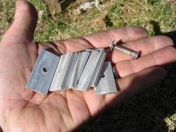 from (1/2 x
3/16)" aluminum flat bar as shown here. Note the relative size difference of
a factory
cupped nut that is on the end of the screw and my home made aluminum washers. I cut the 1/2" flat bar into 1" long sections
and drilled a 7/32" hole in the center of each. Then used Sikaflex
under each washer to provide uniform bedding against the uneven bottom of the
hull flange and under each screw head to seal the holes in the toe rail. This
is a messy job for which a helper is required. Offer copious quantities of
elixir or other suitable bribe after the job is done! Whatever it
takes! from (1/2 x
3/16)" aluminum flat bar as shown here. Note the relative size difference of
a factory
cupped nut that is on the end of the screw and my home made aluminum washers. I cut the 1/2" flat bar into 1" long sections
and drilled a 7/32" hole in the center of each. Then used Sikaflex
under each washer to provide uniform bedding against the uneven bottom of the
hull flange and under each screw head to seal the holes in the toe rail. This
is a messy job for which a helper is required. Offer copious quantities of
elixir or other suitable bribe after the job is done! Whatever it
takes!
To start this job I removed all cushions and cabinets and washed the
settee surface as the best way to see and access the toe rail nuts is to lay on your back
and look up (safety glasses).
I organized the washers,
nylon locking nuts and a nut driver in a parts tray that followed me as the job
moved along the toe rail. I used a nut driver to hold the nut and to push up on the screw to keep the
screw head up off the toe rail till
the last few turns. (Alternatively you could use a tiny ratchet
wrench). Ron, my helper, was outside on a ladder with the Sikaflex and #8
Roberts screw driver to twist the screws in.
 (Don't use an electric
drill as you loose the feel for the required amount of torque to tighten
the screw. Although a tiny torque wrench would be
handy here). While Ron was prepared
to clean up a Sikaflex spill with paper towel and acetone, he discovered that by smearing a ring of Sikaflex on
the thread just below the head, his hands stayed clean, the sealant worked
itself into the top of the hole and best of all, a slight amount of it oozed
out under the head with the last turn. This was his sign that the
screw was tight. I also didn't get any sealant down below
which made my job a lot cleaner. I can't emphasize how
important it is to stay clean when working
with this messy goop. It saved me a
tremendous amount of clean up work, (Don't use an electric
drill as you loose the feel for the required amount of torque to tighten
the screw. Although a tiny torque wrench would be
handy here). While Ron was prepared
to clean up a Sikaflex spill with paper towel and acetone, he discovered that by smearing a ring of Sikaflex on
the thread just below the head, his hands stayed clean, the sealant worked
itself into the top of the hole and best of all, a slight amount of it oozed
out under the head with the last turn. This was his sign that the
screw was tight. I also didn't get any sealant down below
which made my job a lot cleaner. I can't emphasize how
important it is to stay clean when working
with this messy goop. It saved me a
tremendous amount of clean up work,
 not to mention acetone.
The screws were tightened just
to the point where the washers no longer turned. DO NOT over tighten
them to the point of compressing the flange butyl rubber as this adds undue strain
on the flange. (The flange butyl rubber on Panache was
still pliable and looked
as fresh as the day it was applied 28 years ago in 1976.). Above you can
see the original cupped nuts and at right you can see my replacement aluminum
washers and nylon lock nuts.
not to mention acetone.
The screws were tightened just
to the point where the washers no longer turned. DO NOT over tighten
them to the point of compressing the flange butyl rubber as this adds undue strain
on the flange. (The flange butyl rubber on Panache was
still pliable and looked
as fresh as the day it was applied 28 years ago in 1976.). Above you can
see the original cupped nuts and at right you can see my replacement aluminum
washers and nylon lock nuts.
The following notes are important.
- WARNING - DO NOT REMOVE the very aft screw in the toe rail.
The toe rail is under
a lot of strain here as I suspect it was not formed to the hull at installation
time. You likely won't be able to push the rail back in enough to insert the
screw you removed. After I removed the last screw the rail
popped out slightly and it took a real conglomeration of bar clamps
and wood beams to force it back in place. A safer bet is to back
off the screw about a 1/4", replace the cupped nut with a washer
and nylon lock nut, spread some Sikaflex under the screw head and snug
the whole works down. This is good enough and you can call it a
day.
UPDATE - I have since been told
by a fellow sailor in Atlanta that if you remove the most aft
screw first, working stern to bow, it is possible to remove
the end screw, clean the hole and seal the works. He surmised
that the toe rail is held in place by all the forward screws, having
been undisturbed. "Ah the beauty of sharing information openly! If
anyone else has a similar experience I would appreciate hearing
about it."
- To access the rear starboard screws reach through a
hole in the aft, top end of the cockpit locker. Not sure if this
applies to all versions of the hull.
- It took about 3 hours to
complete both toe rails with Panache on the trailer.
NOTE 1: It's not unusual for toe rail screws to loosen
with use. They undergo a huge strain as the hull flexes. Therefore,
you should check them once a year. At
the end of my third season none of the screws have loosened.
Guess this job worked well!
NOTE 2: Eight years after this job most of the screws had to be
retightened. One of the disadvantages of my flat washers is that
tightening the screws is now a two man job. To solve this I have
locked each nut to its washer with a dab of sealant so I only have to spin the screw to tighten the toe rail.
The screw heads were resealed with butyl rubber instead of Sikaflex. TOP
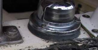
2 - REPLACE the BOW CAP
- (This is an important consideration for this
design) If your bow cap leaks or is beat up beyond repair, it makes
sense to replace it now while the bow is open. See
Tech Tip B12. for the procedure. TOP
3 MOORING CLEATS - You are going to need
the mooring cleats to secure your anchor line to so verify their mounting
with the bow cap off. The factory did not back up the bottom with
extra pads so this is a good time to do so. Round off the corners,
taper the sides of the wood and seal the wood against water absorption.
Also seal the bolts holes through the deck. Finally, coat the bottom
of the cleat and the under side of the screws with butyl rubber.
You'll be glad you did all this in the first storm you anchor in.
Sleep tight! TOP
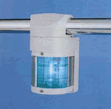
4 - REPLACE the RUNNING
LIGHTS - (This is another important
consideration not to be overlooked). While it's possible to make
the factory deck mounted bow light more visible by raising it on a 3"
tube, it makes no sense to drill a hole through a brand new water tight
bow cap, metal or otherwise, for an ineffective light. Besides, the bow is already
a confined area
to work and you don't need a
delicate protruding light to
make things more difficult. A deck mounted light may meet the current collision
regulations when the boat is level but the reduced visibility with an
anchor or a sail lying on the foredeck is an often overlooked hazard. I also find
that the glare from a deck mounted bow light reflects off adjacent
hardware which reduces my night vision. It makes a lot of sense to
increase your safety with lights that are out of the way and visible
to others at
all times. The improved visibility of the Aqua Signal Series 25 (or
similar) light is night and day over the factory original. They are
equipped with an 8.41MM Festoon bulb for maximum illumination.
With this style of light in mind I offer the following installation
suggestions to improve your visibility:
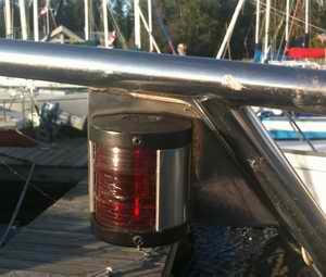
-
 Mount the Lights on a Pulpit Rail - The most expensive but really good
looking method is to
clamp the light to the pulpit (1" OD tubing) using the
manufacturer's rail mount. It's strong, looks very good and is fairly easy
to install. It also hides the wiring if you are clever with a
drill. I'm told this single fixture at the middle of the
lip it is out of the way for spinnaker handling. Unfortunately the
rail mounting is manufacturer discontinued as of 2018. Mount the Lights on a Pulpit Rail - The most expensive but really good
looking method is to
clamp the light to the pulpit (1" OD tubing) using the
manufacturer's rail mount. It's strong, looks very good and is fairly easy
to install. It also hides the wiring if you are clever with a
drill. I'm told this single fixture at the middle of the
lip it is out of the way for spinnaker handling. Unfortunately the
rail mounting is manufacturer discontinued as of 2018.
ELECTRICAL WIRING - To hide and totally protect the electrical wiring, run it
inside one of the forward pulpit legs to the
anchor locker. Drill a 1/4" hole where the light is
mounted and through one foot of the
pulpit. Shown at left is a dual port/starboard light
that requires only one bulb. The SJ23 pulpit is made
from 300 series 1" OD stainless steel tubing (not 316).
Use an aluminum oxide or titanium drill bit (yellowish metal and
harder than tungsten) with water as a lubricant to drill through this
metal. A high speed metal drill bit will go dull very quickly. The closer you drill to the weld bead the harder the metal
is so
drill slightly away from it. If you have two lights, run two sets of wires
down a leg and connect them to the boat harness in the anchor
locker. This makes for easier installation and trouble
isolation. Coil up about 2' of slack wiring inside the locker for future
servicing.
You can thank me later for this!
Use a rubber grommet to protect
the wires from chafe at each access hole and follow up with a dab of Sikaflex
at each light fixture to
keep the water out. Don't seal the bottom hole of the pulpit since it is now a
drain. This job is made much easier with the pulpit off the
boat. You probably have to renew the sealant (butyl rubber) under the pulpit
feet anyway as the factory stuff is dry by now.
-
 Mount the Lights on a Pulpit Plate
- Cut a suitably sized plate of 1/8" thick
stainless steel sheet that fits under the pulpit
horizontal rail just forward of the
post. Either weld the plate or drill some mounting holes through
it to the pulpit rail. Bolt the light on the plate and grind the backs of the bolts smooth so
they don't snag sail cloth. Mount the Lights on a Pulpit Plate
- Cut a suitably sized plate of 1/8" thick
stainless steel sheet that fits under the pulpit
horizontal rail just forward of the
post. Either weld the plate or drill some mounting holes through
it to the pulpit rail. Bolt the light on the plate and grind the backs of the bolts smooth so
they don't snag sail cloth.
 The advantage of this technique is
the added strength and protection for the light fixture. This requires the same electrical wiring as described in
the step above. The advantage of this technique is
the added strength and protection for the light fixture. This requires the same electrical wiring as described in
the step above.
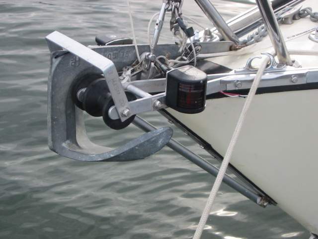
-
Mount the Lights on the Side of the Anchor Roller - If you
installed this anchor roller then it's also possible to mount
Aqua Signal Series 25 lights
on the sides of the roller. You should be able to find a spot that is
clear of the anchor and its line. For those of you interested in
racing, this location clears the pulpit for spinnaker work. Create adequate protection for the lights if you think it's necessary.
NOTE:
Install the lights above the
roller so they don't snag on an anchor or mooring line that is run through
the chocks. The problem is that as the bow rises on a wave, the
mooring line can lift the light off its mount. With the boat "sailing" at the
anchor in deep enough waves it will sheer the lights right off. If the
anchor or mooring lines are run over the roller then this isn't a problem.
-
Mount the Lights to the Side of the Bow - This style of light mounts in the hull just below the toe rail and has the advantage of
keeping the pulpit clear for spinnaker or anchor work. They may not be
as bright as the Aqua Signal light but they are well protected, can be
seen when heeled and
are seldom covered. Choose a very
good quality light that will seal well as it will be exposed to some
direct spray. A plano convex lens
will increase the visibility when mounted on the 160
sides of the bow. Drill a suitable sized hole through the hull into the anchor
locker, run and connect the wiring, seal the fixture to the hull with Sikaflex,
and mount the light. For ease of servicing install a connector
in the wiring harness just behind each light. Grease the
connector pins to prevent corrosion.
- Tri-Colour Masthead Light - While the
visibility of a deck mounted Aqua Signal light is good, a
masthead light is excellent when sailing in deep troughs or as a backup
system. However,
it may be less effective on a small lake where a local boater
may be confused by it or doesn't look for running lights so high up off
the water. If you install dual running lights then you should also
install a switch that sends power to one set of lights only, NOT both. Operating both sets of lights is confusing and therefore illegal.
 Stern Light - While you're at it, replace the original stern light shown here with a
matching Fresnel style. Mount it on a wedge on the transom so the Fresnel
lens is parallel to the horizon or see my solution at
Tech Tip E11. TOP Stern Light - While you're at it, replace the original stern light shown here with a
matching Fresnel style. Mount it on a wedge on the transom so the Fresnel
lens is parallel to the horizon or see my solution at
Tech Tip E11. TOP
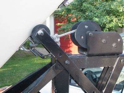 5 -
TRAILER WINCH CONSIDERATIONS - Ensure
that the trailer winch AND the tree roller remain clear of the stem compression
strut when launching. There are two reasons why this anchor roller design doesn't interfere
during
trailer launching; 5 -
TRAILER WINCH CONSIDERATIONS - Ensure
that the trailer winch AND the tree roller remain clear of the stem compression
strut when launching. There are two reasons why this anchor roller design doesn't interfere
during
trailer launching;
-
I pull Panache onto the trailer with the winch
line under the roller as show at right. I discarded the V-block
in the 1990s in favour of a roller that is easier on the
stem.
It rolls very nicely along the stem for launch / retrieval and cups the stem
snug while driving. The slight upward pull lifts the bow when pulling the trailer eye forward
for a snug fit against the bottom of the roller. This way I know exactly
when to stop winching the hull so it is positioned correctly (fore/aft) on the
trailer.
NOTE: With the trailer eye resting under the roller, it can drop away from the roller with ease during a launch and the hull slides
smoothly off the
trailer. With the eye
resting above, it is "hooked" over the roller making it
impossible to slide the hull off the trailer. The hull is
just too heavy to manually lift off the roller. In a
panic stop on the road, the trailer eye under the roller is simply one
more stopper to prevent the boat from sliding forward. Hope I never
have test this theory.
- As Panache is pulled onto the trailer, the bow is also
lifted by a bow roller mounted at the front of the trailer. This lifts the
bow eye directly to the bow roller. See Tech
Tips A01 and A10. Wonderful when it all the
stuff works in harmony.
In conclusion the bottom of the anchor roller stem compression strut just rubs against
the bow roller so the
strut is relatively safe from impact damage. However, the strut must be built robust enough to withstand some force against the
roller. These are two important issues
that
must be considered before contemplating this anchor roller for your boat. I suggest you go through a launch sequence and mark where the roller contacts the
stem. Then install the bottom fitting of the strut slightly above this mark.
Alternatively you
could fabricate a tapered wood spacer that fits snug between the stem and the
compression strut. With concave surfaces fore and aft it should stay in
place quite nicely to support the compression strut. If you launch your boat
with a crane or travel lift then you have no concerns about the bottom location of
the stem fitting. See Tech
Tip A01 about installing a trailer bow roller. TOP
|
|
When making this
roller, keep in mind that the metal must
be bent to conform to the fibreglass, NOT the other way around. See
Tech Tip G03. While this roller looks like a simple assembly you should study the overall design details
very carefully before cutting,
drilling and assembling it. My suggestion is to work from the inside
out to the extremities, starting at the junction point just forward of the
stem head fitting. Cut off any excess metal at the ends to make a
perfect fit. It may waste a bit of material at the ends but it sure saves a
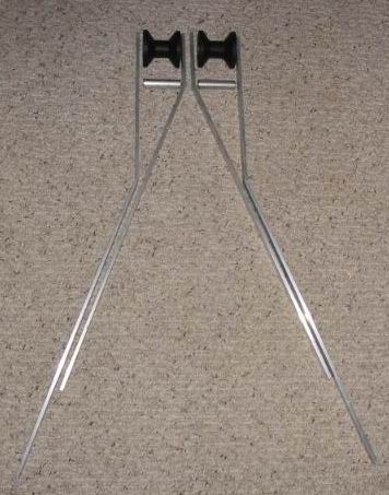
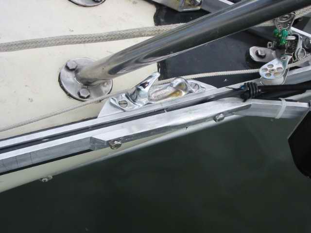
lot of frustration during construction. RAILS - For an
SJ23 the dual roller design requires four 33" long rails to distribute the
loads over as long a section of the toe rail as possible. (While
at least 33" long bars are required to handle a 5kg
Bruce anchor on a 6" overhang, your boat may
require longer rails if your toe rails are cut short from the bow fitting. Try to
get as much overlap on your toe-rails as possible. More overlap means less
loading on the toe rail. Believe it or not, the port and starboard toe-rails are usually not the same
length on most SJ23s).
Make your rails from either stainless steel or
aluminum flat bar (1/4 x 1)". Either metal is strong enough and I
leave the final choice to the builder. My aluminum rails have never
bent. The stainless steel should be
polished and the aluminum should be wire brushed, painted flat black or anodized
flat black to match the toe rail. I painted mine flat black to match the
toe-rails.
-
 INSIDE RAILS - Form the two inside rails first.
Place a rail along the inside of a toe rail to mark the position for the
bend, which is just forward of the stem head fitting.
Actually the size of your anchor determines how much rail should
protrude forward of the stem and hence the position of the rollers.
What's at issue here is to keep the anchor fluke off the bow. Fit the
other inside rail. Use a
strong vice and a heavy hammer to bend each rail. Clamp the rails
together at the front and check the fit while they lie on the bow.
Make sure that the forward protruding section of the rails are parallel
with the center line of the hull and rest flush against each other.
This is absolutely crucial. As a check, both rails should have equal symmetrical
bends of about 200 each. INSIDE RAILS - Form the two inside rails first.
Place a rail along the inside of a toe rail to mark the position for the
bend, which is just forward of the stem head fitting.
Actually the size of your anchor determines how much rail should
protrude forward of the stem and hence the position of the rollers.
What's at issue here is to keep the anchor fluke off the bow. Fit the
other inside rail. Use a
strong vice and a heavy hammer to bend each rail. Clamp the rails
together at the front and check the fit while they lie on the bow.
Make sure that the forward protruding section of the rails are parallel
with the center line of the hull and rest flush against each other.
This is absolutely crucial. As a check, both rails should have equal symmetrical
bends of about 200 each.
-
HOLES
- Drill
the holes for the horizontal box bolts and compression sleeves that
will be installed just forward of the junction of the inside rails. Bolt the rails together temporarily.
(In a
job like this I find that the end results are much more accurate when
a bolt is temporarily installed through a hole to maintain alignment
and prevent movement. Finally, mark and drill the remaining holes). Temporarily clamp the rails to the inside
of the toe rail. Stand back to see if the rails are still
parallel to the center line of the hull and flush to each other.
This is absolutely crucial. It helps to stretch a
dark string along the center line of the hull as a guide. Drill the
holes for the forward box bolt. Release the clamps.
-
Place the stem compression strut between the inside rails. Insert an
equal thickness spacer at the inner hole. Bolt the two rails together temporarily with
a couple of bolts. Fit the assembly on the deck again. This time pull
the assembly forward to fit the rails snugly against the inside of the
toe rail. Check for alignment.
-
OUTSIDE RAILS - With the inside rails still on
the bow, fit a compression sleeve against one of the inside rails and
extend an imaginary line from the outside of the roller back to the toe
rail to determine the location of the bend for the outside rail. Use a wood spacer to make this job easier. Keep in mind that
the forward protruding portions of all four rails must be parallel to
each other so the rollers can turn freely. Bend the
outside rails (approx 200) and place them against the
outside of the toe rail. Clamp the assembly to the toe rail and mark
the position for drilling the holes for the box bolts. Drill the
holes. Assemble and tighten the forward section of the assembly.
-
 Fit the tightened assembly to the bow ensuring that
the anchor roller fits snug to
the toe rail. It is crucial that the roller rails fit snug to the
toe-rail. Clamp it in position for marking the toe-rail mounting
holes. You'll require tapered spacers to fill the void
between the edge of the angled toe-rail and the roller rails. Drill the holes and install
the mounting bolts. You MUST install a
bolt with a spacer at the junction of the inside and outside rails to stiffen the structure. Check for alignment. Fit the tightened assembly to the bow ensuring that
the anchor roller fits snug to
the toe rail. It is crucial that the roller rails fit snug to the
toe-rail. Clamp it in position for marking the toe-rail mounting
holes. You'll require tapered spacers to fill the void
between the edge of the angled toe-rail and the roller rails. Drill the holes and install
the mounting bolts. You MUST install a
bolt with a spacer at the junction of the inside and outside rails to stiffen the structure. Check for alignment.
-
Disassemble the entire roller and reassemble it using Sikaflex at
all bolt holes. Tighten the entire assembly in place. TOP
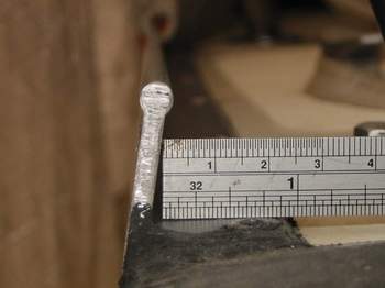
BOX BOLTS & COMPRESSION SLEEVES -
A box structure, consisting of flat rails held together by threaded ready rod
covered with aluminum compression sleeves around them, is very strong and
light weight. Once the nuts are tightened against the compression sleeves
the structure becomes extremely stiff. In the photo below you can see that
I used two bolts with compression sleeves around them. This is the minimum.
The compression sleeve around the forward bolt is also the bearing for
the rollers. The decision to incorporate two
or three box bolts is largely dependant on the length of the rails to
support and fit to your anchor
stock. The idea being to keep the business end of the anchor away from the hull while
making the structure very rigid. Use thick walled tubing
 for a sleeve. Cut each sleeve so it is 1/8" longer than a roller. Use minimum 5/16"
OD stainless ready rod for the box bolts through the sleeves as stainless
steel bolts this long are not readily available. So cut the length of
the ready rods to have about 1" of rod sticking out each side, allowing
for a spacer (sleeve) to be placed between the inside rails.
In the interest of being able to effect repairs in the field with simple
tools, the nuts should be placed on the outside where they can be easily tightened.
One technique is to use a nylock nut tightened against a half nut (double
nut) at one end
of the rod (or tack weld a nut to the end of the rod). Then use a single nylock nut at the opposite end.
Once tightened, cut off any excess rod protruding beyond the nuts, leaving
no exposed thread to snag a line. Finally cap the nuts with nylon caps or
stainless cap nuts to provide protection. TOP for a sleeve. Cut each sleeve so it is 1/8" longer than a roller. Use minimum 5/16"
OD stainless ready rod for the box bolts through the sleeves as stainless
steel bolts this long are not readily available. So cut the length of
the ready rods to have about 1" of rod sticking out each side, allowing
for a spacer (sleeve) to be placed between the inside rails.
In the interest of being able to effect repairs in the field with simple
tools, the nuts should be placed on the outside where they can be easily tightened.
One technique is to use a nylock nut tightened against a half nut (double
nut) at one end
of the rod (or tack weld a nut to the end of the rod). Then use a single nylock nut at the opposite end.
Once tightened, cut off any excess rod protruding beyond the nuts, leaving
no exposed thread to snag a line. Finally cap the nuts with nylon caps or
stainless cap nuts to provide protection. TOP
ROLLERS
- Having two rollers is perfect for the night you need to anchor
with two hooks down or to hang on a mooring with two lines. If you buy none standard rollers, it's a wise idea to buy some extras. You can never
tell when the stock will run out. You could also machine your own
rollers from aluminum or other hard material but that's getting
anal!
-
A 5Kg (15 lb.) Bruce anchor has plenty of holding power for an SJ23
and fits just fine on a 2" diameter trailer roller that's about
3" wide.
-
The hole through the roller should be equipped with a Delrin bushing and it should
fit just over the compression sleeve so it turns freely under load.
Consider the roller as the outside of a bearing that runs on the
compression sleeve.
-
The bushing should be cut slightly longer than the roller such that
when the nuts are tightened against the sleeves, it leaves at least a
1/16" end gap.
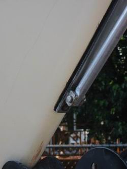
If you position the forward rollers so the sides protrude beyond the
forward ends of the rails they can absorb some impact if you hit something. This
might just be enough to cushion against a dock to save your toe rail from
crushing. A
typical scenario would be when slipping bow first into a dock and not
stopping in time. (i.e. using the dock to stop the boat!). On the other
hand, you loose some side support on the end of a roller to handle an angled anchor
line. This is a typical action when the boat starts to see saw in the wind as you
pull up
anchor. If you install the rollers so they protrude, leave enough
metal in the rails to maintain strength and to mount the bail. TOP
BUNGEE CORD -
To prevent your anchor from prematurely launching itself off the roller it
is recommend to use a
light line or bungee cord (shown laying loose above) hooked to the retrieving hole of
the Bruce anchor. It should go without saying that you
should always keep your
anchor attached to the anchor line and it wouldn't hurt to
firmly secure the other end of the line to the inside of the anchor
locker! TOP
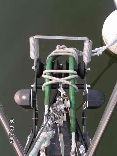 ADJUSTABLE BAIL - The purpose of
the bail over the roller is to keep the anchor line captive over each roller when
bouncing in four foot waves. If you fabricated the bail from 1/4"
thick stock you'll appreciate the benefits the first time you
have to anchor in rough water! It can really take the abuse from anchor or mooring lines. If the line
should slip off a roller and onto the bar stock between the roller, it
will quickly saw through, leaving you floating free with the
anchor firmly stuck in the bottom somewhere! I will add a round vertical
divider between the rollers (from the bail to the frame) to keep the anchor
line over its roller. This modification is not shown in this picture. In
the mean time I have rounded the inside of the bail to prevent chafe when the hull lies sideways
to the anchor line. ADJUSTABLE BAIL - The purpose of
the bail over the roller is to keep the anchor line captive over each roller when
bouncing in four foot waves. If you fabricated the bail from 1/4"
thick stock you'll appreciate the benefits the first time you
have to anchor in rough water! It can really take the abuse from anchor or mooring lines. If the line
should slip off a roller and onto the bar stock between the roller, it
will quickly saw through, leaving you floating free with the
anchor firmly stuck in the bottom somewhere! I will add a round vertical
divider between the rollers (from the bail to the frame) to keep the anchor
line over its roller. This modification is not shown in this picture. In
the mean time I have rounded the inside of the bail to prevent chafe when the hull lies sideways
to the anchor line.
NOTE: If the boat is moored for any length of time, the
mooring lines should
be secured over each roller with a short length of line tied around them to
keep the lines over the rollers. Use a square
lashing. Care must be taken that the
mooring load is held by the mooring cleat on the deck, not the lashing. This is
another reason why the rollers should be made of hard rubber and be equipped
with an internal Delrin bushing. You don't want them flattened under load!
The angle of the bail should be adjustable so the anchor line
doesn't rub against the underside of it when it is hauled in.
NOTE:
As a side note, the boat lies much quieter at the mooring or anchor with the lines over the rollers shown here as opposed to the lines through the mooring chocks as shown above. TOP
STEM COMPRESSION STRUT - The
30" long (approximate) stem compression strut (tube with flattened
ends mounted between the frame and the stem) may be made to the exact
length (if you are good with a measuring tape) or made telescopic with two
 through
bolts to lock it to the final length (if you want to save time). The outer
tube should be the top one to let water drain out. The bottom one should
have a small drain hole just above where it is flattened. This tube also
resists a substantial amount of lateral torque to add rigidity
to the frame. through
bolts to lock it to the final length (if you want to save time). The outer
tube should be the top one to let water drain out. The bottom one should
have a small drain hole just above where it is flattened. This tube also
resists a substantial amount of lateral torque to add rigidity
to the frame.
-
The stem strut takes the vast majority of the downward load when
anchored so the bottom end should be fastened about 10" above the trailer eye, to a bolt drilled through the stem.
Consider where the trailer roller will rub on the stem during launch.
Review and understand this thoroughly.
IMPORTANT
- The bottom of the strut MUST NOT be mounted to the stem head
(forestay) fitting unless you are the type who enjoys watching your mast come
down due to a loose or missing bolt from the last force 8 storm! By
installing the stem fitting independent of the anchor roller, the loosening of the roller cannot result in the collapse of
the standing rigging!
-
The top end of the strut must be installed between the
rollers for maximum mechanical advantage (two box bolt design). Failing that, install it just back of the rollers (three box bolt
design).
-
With the top of the strut bolted between the rails swing
the bottom end against the stem fitting and mark the exact location of
the stem
mounting bolt hole. Drill a pilot hole through the stem.
-
Make a backing block from hard wood that fits against
the inside of the stem, in the anchor locker. Taper the top of
the block so all the water can drain off the wood. Round off all
corners so no anchor line can snag on it. Soak the block in epoxy to seal it
from wood rot.
-
Hold the backing block (inside the stem) over the
pilot hole and drill
the final size. Drill through both for correct alignment. Install the bolt
through the stem fitting and backing block using a
substantial washer, then tighten the nylock nut. Use butyl
rubber to seal
the holes.
-
Finally, if you use telescopic tubes for the compression strut,
drill two holes through the two tubes to lock the overall length.
The holes for the two bolts that lock the tubes together are drilled
last when all is fastened securely. TOP
|
|
HOLDING IT ALL TOGETHER
|
| FASTENERS - Use nylon
lock nuts to prevent the parts from coming loose.
ADHESIVE - Apply a high quality
marine adhesive such as Sikkens Sikaflex, 3M 5200 or butyl rubber between the bars and the toe rail
to keep water out and prevent marine growth. The adhesive will also inhibit
galvanic action if you use stainless steel bars against the aluminum toe
rails. See Tech Tip G01.
NOTES:
- The final assembly of this roller is best done with two people. Unless you're a masochist you simply don't have enough hands to hold
all the pieces in alignment on the curved surface. But then most
complex jobs always go easier with more hands, unless the others hands
are holding beer! TOP
|
|
SELECT ANCHOR LINE BASED ON YOUR
LOCAL CONDITIONS |
| |
3
STRAND NYLON |
3
STRAND
POLYPROPYLENE |
| Line Diameter |
Safe Working Load (lbs) |
Breaking
Strength (lbs) |
Safe Working Load (lbs) |
Breaking
Strength (lbs) |
| 3/8" |
680 |
3,400 |
540 |
2,700 |
| 1/2" |
1400 |
7,000 |
820 |
4,100 |
| 5/8" |
2120 |
10,600 |
1240 |
6,200 |
| 3/4" |
3000 |
15,000 |
1700 |
8,500 |
NOTE
- safe working load = 1/5 of breaking strength.
|
Panache currently has 175' of 5/8" yacht braid and 25' of chain with a 5Kg Bruce anchor for ground tackle. Great security for a peaceful
night at anchor.
|
|
ANCHOR STORAGE OVER FORWARD BERTH (2014) |
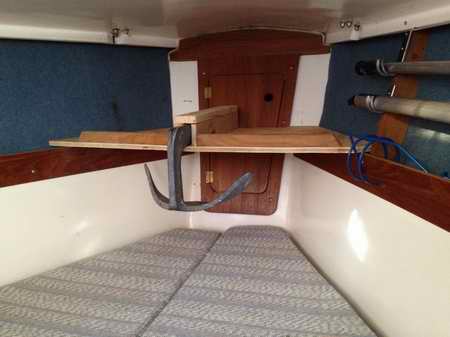 When
I'm at my mooring
or day sailing
I store the anchor on a tri-angular storage shelf that rests on the
fiddles at the forward end of the V berth. This keeps it off the
cabin floor where it was a royal PIA since I stubbed my toe on
it a lot. I was quickly developing a love / hate
relationship with that chunk of steel. In 2014 I decided to do
something about that relationship with a temporary shelf to fit above the
forward berth. Then I added a 1.5' long slot from two parallel strips of wood
and fastened it on top of the shelf to receives the
stock of the 5Kg Bruce. The snug fit keeps the anchor from rolling. I thought a bungee cord
around the end of the stock would be needed to keep it there, but that is not the case. It never moves. When
I'm at my mooring
or day sailing
I store the anchor on a tri-angular storage shelf that rests on the
fiddles at the forward end of the V berth. This keeps it off the
cabin floor where it was a royal PIA since I stubbed my toe on
it a lot. I was quickly developing a love / hate
relationship with that chunk of steel. In 2014 I decided to do
something about that relationship with a temporary shelf to fit above the
forward berth. Then I added a 1.5' long slot from two parallel strips of wood
and fastened it on top of the shelf to receives the
stock of the 5Kg Bruce. The snug fit keeps the anchor from rolling. I thought a bungee cord
around the end of the stock would be needed to keep it there, but that is not the case. It never moves.
However, when I sleep up there
I think I'll flip the anchor over to create some room for my tootsies!
|
|
MY FIELD OBSERVATIONS |
I always have apprehension when a new critical component such as this anchor roller is
installed on Panache. I don't have sheltered water to move
Panache to in case of a trouble and since she looks after herself everything must work the first time, all the time! During the
first season I used this roller Panache experienced a two day 30 knot
storm, a 60 knot storm that lasted for 2 hours and a force 9 gale that lasted for about an
hour. I'm happy to report that all the new components survived
unscathed.
So
far I like this roller very much and have no problem recommending it.
The following are my observations with regard
to Panache lying at her mooring:
- If the mooring lines are run over the
rollers, they lay fair with no interference or undue strain. In
fact the hull
hunts less than with the lines through the chocks. I use a 2' long
rubber garden hose over each of my mooring lines as anti chafe gear.
- If the mooring lines are run through the chocks, they lay fair with no
interference but with more strain due to sharper turning angles.
- If
the mooring lines are run through the mooring chocks
with the Bruce anchor laying on a roller, then the lines will
rub against the flukes as the hull hunts in a 30 knot wind.
However, this requires the
correct combination of waves, wind and angle of the boat.
From the above observations you can see the advantage of running the mooring lines over this
anchor roller and is the reason why I store my Bruce anchor inside the
cabin on a storage shelf.
- On
one occasion I was anchored in 30' of water in a real nasty gale
(force 9 judging by the state of the water) for about 30 minutes, after which it blew out, thank God. There was 4 miles of open water upwind of Panache. We experienced
very steep 4' high waves with dense foam and wave crests rolling over
the bow. The visibility was severely reduced by the spray and spindrift. In these conditions Panache
was blown sideways to the anchor line causing me much concern for an
untested anchor roller and possible line chafe over the edge of the bail.
Fortunately the line did not wear through and the roller assembly survived the test with flying
colours. However, I later strengthened and rounded off the inside of the
adjustable bail to protect the line.
NOTE: If a boat lays sideways to
the anchor, you are almost guaranteed to be dragging the anchor. If the boat is pointed to the anchor, within 750, the anchor is still holding.
- If
you intend to install running lights on the side of the roller assembly, then install
them above the rails, not below. The problem is that as the bow dips down
in a trough, the bottoms of the lights are pushed down on the mooring lines. With deep enough troughs
the lines will sheer the lights off the
roller. Damn that's expensive.
- I
experienced another situation that reassured my faith in the SJ23 hull
to deck joint construction. A Swiftsure 21 was lying adjacent to an SJ23
after its mooring became entangled with the SJ23 mooring during a storm. Two unequal weight
boats will never have the same motion in the same waves. In the out of
sync up/down motion
of the boats, the toe rail of the SJ23 rose to sheer off the Swiftsure rub rail and broke the fibreglass
deck off. The only damage to the SJ23 was a bit of gel coat rubbed off. The whole bow of the Swiftsure
was opened from shroud to stem. This demonstrates
how incredibly strong the hull to deck joint of an SJ23 is.
- Once this
bow roller was attached to the stem the bow simply became much stronger. If
you use nylock nuts, there
should be no fear of the roller hardware loosening in a storm. I
now moor Panache with the pendants over the roller, I have that much confidence
in it. Nice thing is, she rides quieter.
- And finally, if you think you may want a bow sprit in the future , it
might be a good idea to incorporate it in the frame work of this roller.
A bow sprint is a great place to attach the tack of a cruising spinnaker
equipped with a top down roller so you can leave it furled while sailing upwind. I
haven't thought this design through yet but considering it. I'd
welcome your suggestion. TOP
|
|
Return
to Tech Tip Index. . . . . . . . . . . . . . . Have
a Question? |
 I've
seen so many different techniques for installing a mooring chock that it's
beyond my keyboard pounding skills to describe how to incorporate your existing
installation with this anchor roller. If the mooring lines are run over each roller then the boat hunts
less. This is due to the attachment
point being forward of the hull which negates the need for chocks at a
mooring. (The
final verdict is that the hull hunts
less).
However, I still like
the ultimate strength of properly installed mooring chocks, even if they
are only a backup. I've installed my chocks as far forward as possible so
the boat rides easier at the mooring. I also
use a chock when tied to a dock.
The mounting screws for these chocks are 3.5" apart and the chock is cable
of holding 1" line or 1/2" line with a garden hose over it. There is
nothing better than rubber garden hose for chafe protection.
I've
seen so many different techniques for installing a mooring chock that it's
beyond my keyboard pounding skills to describe how to incorporate your existing
installation with this anchor roller. If the mooring lines are run over each roller then the boat hunts
less. This is due to the attachment
point being forward of the hull which negates the need for chocks at a
mooring. (The
final verdict is that the hull hunts
less).
However, I still like
the ultimate strength of properly installed mooring chocks, even if they
are only a backup. I've installed my chocks as far forward as possible so
the boat rides easier at the mooring. I also
use a chock when tied to a dock.
The mounting screws for these chocks are 3.5" apart and the chock is cable
of holding 1" line or 1/2" line with a garden hose over it. There is
nothing better than rubber garden hose for chafe protection.