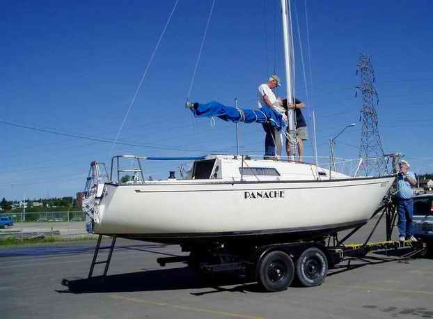
 Panache
has undergone many modifications to make life more comfortable
in the cockpit and safer on deck. The most challenging and rewarding was the conversion of the corner stanchions to a pushpit in 1998. Here's why: Panache
has undergone many modifications to make life more comfortable
in the cockpit and safer on deck. The most challenging and rewarding was the conversion of the corner stanchions to a pushpit in 1998. Here's why:
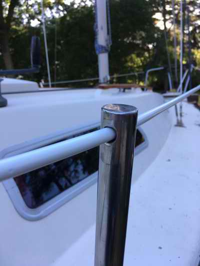
- I always considered the factory
cockpit
corner stanchions lethal if I were to fall on one. For this reason alone the design would never be accepted in industry today and was my primary motivation to fabricate a pushpit.
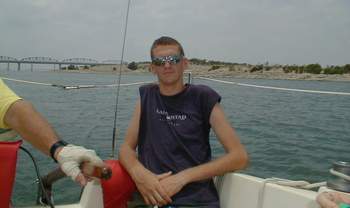
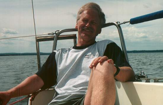
- The post is also uncomfortable to lean against. You can see Carey resting against a corner post with his spine to one side of the post. You
learn this trick pretty quickly when the pain tells you to move sideways! While this is not the most comfortable
position in the
world, it is better than nothing. Slipping off the critical position can hurt
the vertebrae which is
another reason why I
decided to get rid of the corner stanchions.
- My third reason for building the pushpit is to create lifeline gates. This way I
don't have to do a potential life altering pirouette over the life line to step on/off the dock.
- This conversion also eliminates the hassle of having to latch the pelican hook in mid air. I always found this difficult when I had to pull the lines around the corner stanchions with netting tied to the toe rail at the bow.
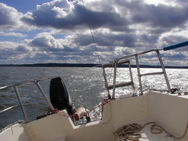
- I consider it the height of luxury to sit on the low side of the cockpit at hull speed, wedged in the corner against the cabin wall with my legs stretched along the bunk. Inevitably my head ends up resting against the cabin so my head is as one with the motion of the hull while staring at the wake. The view over the transom is mesmerizing, especially with a
setting sun.
Unfortunately, it is "somewhat difficult" to see forward from
this position. Since I sail solo a lot I built this pushpit so I can
be just as comfortable facing forward. What a novel thought!
 PUSHPIT
DESIGN
CRITERIA
(1998)
- I
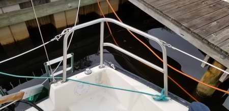
think a SS pushpit is one of those things where art follows function. I designed this pushpit to be proportional to the hull and
parallel to the major hull lines so it looks good.
It has to be pleasing to the eye, comfortable to lean
against,
functional and extremely strong so a person can stand or sit on it. I
tend to do the odd acrobatic stunt while onboard!
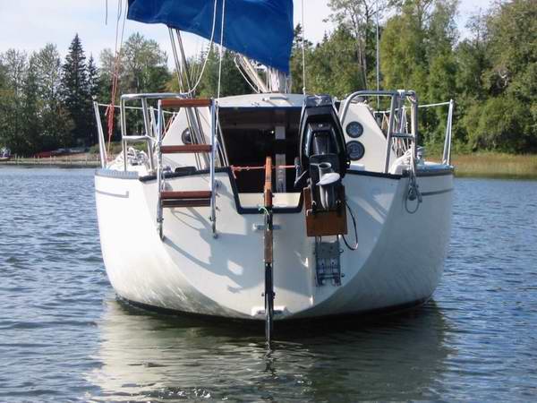
Don't ask. To fit this criteria I decided on a split pushpit with a transom gate made of SS lifeline closed with a pelican hook. A one piece pushpit is actually easier to make. A split
pushpit creates
relatively easy access to the
outboard, has easy boarding from the transom ladder, has rounded edges for
safety and leaves room for a future
split backstay tension adjuster. PUSHPIT
DESIGN
CRITERIA
(1998)
- I
think a SS pushpit is one of those things where art follows function. I designed this pushpit to be proportional to the hull and
parallel to the major hull lines so it looks good.
It has to be pleasing to the eye, comfortable to lean
against,
functional and extremely strong so a person can stand or sit on it. I
tend to do the odd acrobatic stunt while onboard!
Don't ask. To fit this criteria I decided on a split pushpit with a transom gate made of SS lifeline closed with a pelican hook. A one piece pushpit is actually easier to make. A split
pushpit creates
relatively easy access to the
outboard, has easy boarding from the transom ladder, has rounded edges for
safety and leaves room for a future
split backstay tension adjuster.
NOTE -
While I like a pushpit corner seat like those on a wide transom boat these
days, I rejected them for an SJ23
due to the narrow stern. There just isn't enough
buoyancy to carry four adults in the cockpit, let alone a crew sitting on the
pushpit. I realize it may afford a grand view
but it will raise your head above the bottom of the jib, defeating the purpose of sitting that high.
You really should stay within the safety of the cockpit when sailing
solo, which means keeping your feet on the cockpit sole. I wouldn't necessarily discourage a person from
installing a seat, just remember to manage your expectations.
The following
guidelines are
specific to the design with the water line horizontal:
-
SS TUBING -
Use 1" OD (25 MM) stainless steel ornamental tubing to match
the pulpit. Ornamental tubing is well within the strength
requirements and the thinner walls bend relatively easy, making it
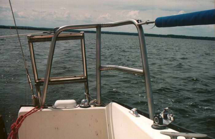
possible to create a kink free 3" radius bend. A 3" radius bend
fits
perfectly around my head as shown below, making a very
comfortable rest.
NOTE - It is very difficult to describe in XYZ terms the
dimensions and angles of this pushpit since it rests on a curved
surface. This is more about art than structural engineering! For the purpose of this description the horizontal sections
of the pushpit are called rails and the vertical sections are
called legs.
-
 TOP
RAIL - The top rail, to the right of my head, is parallel to the top of the
transom. TOP
RAIL - The top rail, to the right of my head, is parallel to the top of the
transom.
- The top rail to the left of my head is parallel to the toe rail.
The tops of both rails are 17.5" above deck. This is
slightly higher than the height of the lifelines (16.5") so the pelican hooks
can latch just below the top. This way the
life line forms a gentle curve, parallel to the toe rail. The
lifeline attachment ring leaves no sharp projections.
- When
bending the stainless tube ensure that port and starboard
upper rails have a symmetrical spread of 1030 each.
I found this to be a painstaking job given the compound angles.
-
LOW RAIL -
The lower horizontal
rail is
parallel to the upper rail and
9" above deck, making it very comfortable to lean on or against. While
not totally required it sure adds comfort. Now we're getting
somewhere.
-
AFT INSIDE LEG
- The angle of the aft inside leg (behind my right shoulder) parallels the
side of
the companionway, about 130 off vertical. Or you
could parallel the slope of the tiller cut out which is
easier to copy. Your choice. The two are almost parallel. The fore/aft angle is about 100 aft
with the boat floating. The horizontal angle
between the rails is 1030.
-
MID LEG - The angle of the
middle leg is about
100 aft
with the boat floating.
It can easily support the weight of a person standing on it or leaning
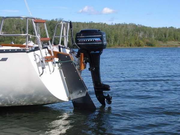
against it. The location of this post creates minimal
restriction to access the outboard.
-
FORWARD LEG - The
fore/aft angle of the forward leg, behind my left shoulder, is
1050. The sideways angle follows the
curvature of the
hull.
Cut
all legs over length by a few inches. This gives you the extra
material to fit the pushpit at precisely the correct height and angle to the deck. This is
real painstaking work so take your time.
It is easy to build the first pushpit "perfect," but real difficult to
build a second pushpit that is a perfect mirror image. For this
reason, fit the side with the shorter legs first. Long legs can always
be cut shorter, but short legs, never!
-
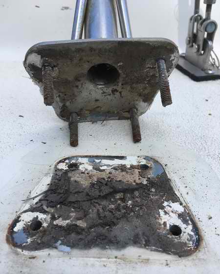
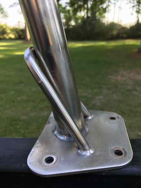
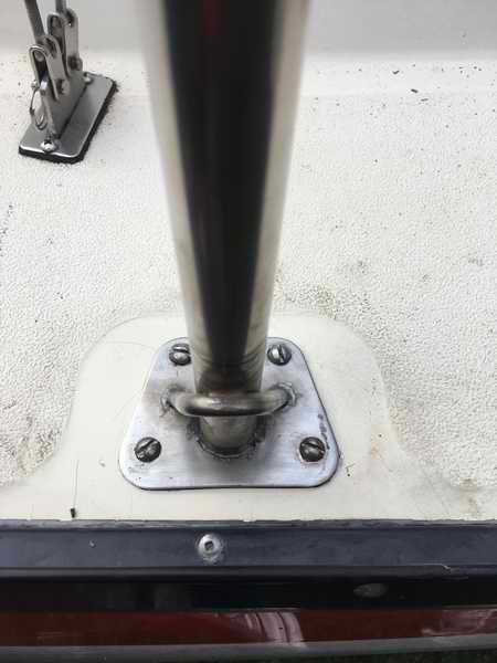
FEET - Make
the
feet from 1/8" thick stainless steel flat bar, (1x2)", welded to the bottom of each
post so it is parallel to the deck for secure bolting. Each foot has three 1/4" holes drilled it.
A 1/4" holes through
each end to bolt to
the deck or through the toe rail and one immediately under each tube to
relieve the internal air pressure for welding. It can be left open
as a vent
hole or to run electrical wiring through if you wish. I sealed mine with
goop.
Later
I may run wires through it for navigation lights.
-
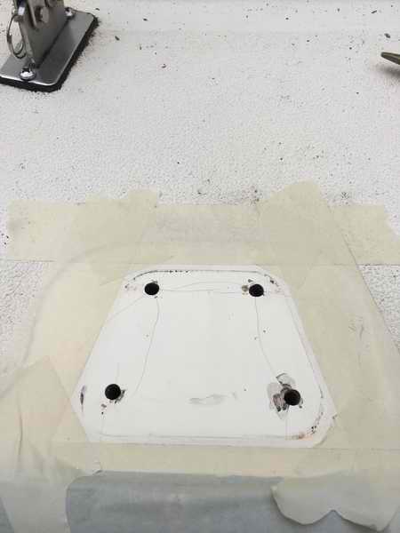
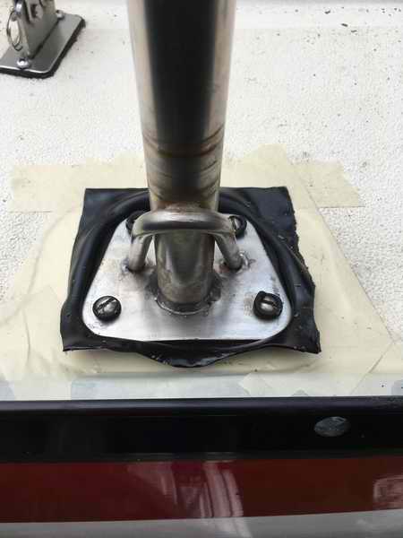
SEALANT -
Use plenty of Sikaflex marine sealant or butyl rubber under each foot
and under the bolt heads or the cockpit lockers will slowly fill with
water. Use 2" long
bolts to facilitate assembly with nylock nuts and the biggest
fitting washers you can find. The washers will help to retain sealant as you tighten the
bolts.
FINAL FIT
- When you look
over the pushpit (across the cockpit) the port and starboard rails and
legs MUST be parallel to each other. (This step is very important
because the dock watchers will scrutinize your workmanship).
- The
tubing may be polished
to match the pulpit but I doubt you can match the shine of the
factory finish. I'm quite sure the factory finish is
chemically polished because that process produces a chrome like
finish.
The welding is sure nice. The other polishing technique is to
buff the metal with lapping cloth which could be quite an ordeal, given all the curved
surfaces. Polishing will improve the
resistance to corrosion by removing the microscopic fissures that trap
debris. I think polishing would be easier with the units still
off the boat.
TOOLS
- It
is a tricky task to fabricate two symmetrical units and
then mount them on a curved deck so they are parallel to each other, the
deck surfaces and the cabin lines. One screw
up
in the mounting stage and all your perfect bends during fabrication go
down the drain. It think I can quite safely say that I
measured ten times for each bend or cut, maybe more. There are three
tools I found to be very handy.
-
A pointer stick that can be temporarily clamped at any angle to the
tubing to simulate a mid rail or leg. This
is a very quick and accurate reference guide to aid in positioning
tubing at the correct place and angle. I don't know of a
commercial made tool so I made one from a hose clamp tightened over a piece of
bent flat iron. A mitre bevel can work well but it doesn't stay in
place.
-
A fine point "Sharpie" to mark the tubing. The ink washes off
SS easily with acetone.
Writing on masking tape works well too but remember to wash off the
adhesive before welding. A pencil is useless. Several years after this job my son showed me a Sharpie
designed for stainless steel. Sure wish I knew about this back
then.
- Another handy tool that I
currently own but didn't know about at the time, is a Unitek
Magnetic POLYCAST Protractor. It measures angle in degrees
relative to the center of this planet (gravity), similar to an inclinometer. (Its used to set the angle of elevation for a satellite dish). The ~10 accuracy is very
useful for transferring angles from port to starboard to measure
symmetry, provided the boat is absolutely level.
 CONSTRUCTION
- Bending SS
tubing must be done with a bender designed specifically for the
properties of SS. It pulls the tubing around the mandrill,
instead of squeezing it around the corner that is the technique used for
bending conduit. SS benders are almost always power
assisted or have a long lever for mechanical advantage. It takes a lot of force to bend SS tubing. The one I used was mounted on a waist high work bench and came
with a 6' long lever. Ridgid
makes a geared ratchet portable tube bender that just might work for
you. I have no
experience with this tool but it looks promising. Keep in mind
that the bending radius is set by the diameter of the mandrill and the
inside of the mandrill must
match the diameter of the tubing. It takes skill and a lot of setup time to produce good results. CONSTRUCTION
- Bending SS
tubing must be done with a bender designed specifically for the
properties of SS. It pulls the tubing around the mandrill,
instead of squeezing it around the corner that is the technique used for
bending conduit. SS benders are almost always power
assisted or have a long lever for mechanical advantage. It takes a lot of force to bend SS tubing. The one I used was mounted on a waist high work bench and came
with a 6' long lever. Ridgid
makes a geared ratchet portable tube bender that just might work for
you. I have no
experience with this tool but it looks promising. Keep in mind
that the bending radius is set by the diameter of the mandrill and the
inside of the mandrill must
match the diameter of the tubing. It takes skill and a lot of setup time to produce good results.
Most of the SS tubing I've seen has a longitudinal line on the outside. I think this is a result of the manufacturing process. If your tubing doesn't have a reference line, draw one with a "Sharpie" (felt pen). Use the line to assist you for marking a reference. The line can be used to determine the start and finish of a bend and the correct axis of the bend. Without it, you will be spending tons of time orienting the tubing with each bend, which is very frustrating to say the least. You will be doing lots of double checking anyway and this reference line sure makes the job
easier. The line also helps to keep you oriented to the tubing as it is all too
easy to confuse port for starboard, fore for aft and up for down. Another slick trick is
to mark each unit with tape for port/starboard and fore/aft
reference. I learned all this on my second unit which I bent in one third
the time of the first unit.
FITTING to the DECK
-
Unfortunately I miss placed my plans. I built
the pushpit before I ever
decided to publish these Tech Tips. They were written on
restaurant napkins and scraps of paper. As I recall, I started fitting each
corner assembly to the
transom first, then worked my way forward. I adjusted the
position and angle of the first assembly till it was parallel to the companionway
opening and the cockpit lines. Then I adjusted the position and angle of the second
assembly till it was parallel to the companionway, cockpit lines, and
being symmetrical to the first unit. A tricky business to say the
least. You might have to juggle both assemblies a bit to make a happy
compromise for symmetry. Symmetry and parallel is very important
though.
It might help to attach both units to a straight plank placed across the top
to lower the assemblies on the deck. While the
exact lengths of the legs were marked with masking tape, I
cut each 1" longer than required just to be safe. I placed them
on the deck to determine if there were any inaccuracies. I
used this technique to incrementally cut each assembly to the correct deck
height so they were symmetrical. A very painstaking, tedious process. If I were to fabricate
them again I would make plywood moulds to form the tubing
around and attach two posts to the toe rails to run alignment strings
across the cockpit. This would give me a reference line elevated from the deck
surface without the need to constantly measure with a tape.
Having figured out the dimensions at home I did all the tube bending at
a shop where a friend loaned me the use of their bender. Coffee
for the guys was cheap! In the absence of a mould the feet
were welded in place with Panache backed into a welding shop. It was raining at the time and no welder will stand in a puddle of water
while the stick is lit! So I just backed her in through the overhead door. To say that my project captured the
interest of the entire shop is the understatement of the year. Fact is,
with Panache in the shop they couldn't do anything else anyway and with this
many "experts" running around you just can't go wrong.
Two guys holding SS in place while the welder tacks it is not
to be discounted. I was directing the show and ordered
coffee, again! Once I got the two pushpits home I hammered the feet slightly
till they fit flush to the deck. As a weld cools it has a
tendency to shrink and pull metal away from the original position.
Afterwards I ground each weld smooth and polished the metal.
You should be able to reverse engineer this pushpit from the
photos and the description here. If you would like more detail pictures, just email
me quoting this Tech Tip.
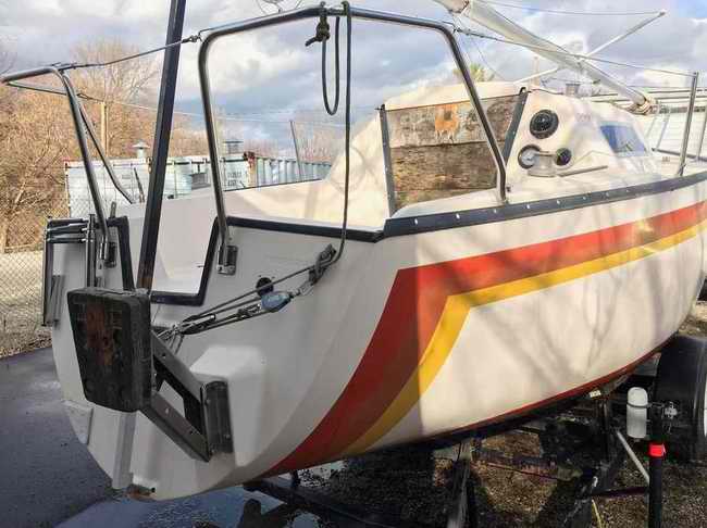
CONCLUSION
- After sailing
several years with the split pushpit I can report that life on board is easier with increased safety and comfort in the cockpit.
Access
from a dinghy or dock to the cockpit is quicker as it is now a simple
matter to release the pelican hook in front of me. I am still
amused when another SJ23 owner steps on board and is amazed with
how easy it is to open or close a gate. The hazardous corner posts are
replaced with smooth tubing that is strong enough to stand on and
is definitely comfortable to lean against. As a surprise, the
cockpit has become a bit roomier because the lifelines are now slightly further
outboard. I can now sit on the
coaming and rest against the life line for a better view forward. This is definitely one of
those situations where all the little modifications combine to create a significant
improvement for safety, comfort and convenience.
PS: It also looks better than corner posts.
In these photos I have yet to fabricate the life line gates.
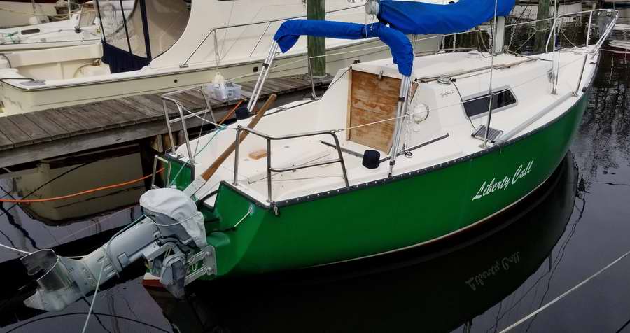
Click here to see Liberty Call's
split pushpit, proving that this pushpit can be reverse engineered.
NOTE
- Back
in the days when Clark owned San Juan, a company called
Railmakers Northwest built all the rails, stanchions, etc. They did nice work and
had patterns for the tooling, so pulpits and what-not just bolted on. They are still located on the Everett, Washington waterfront (near the boat
ramp).
_______________________________________________________
 LIFELINE
GATE
- I never did like the
way the original lifeline dropped to the deck when the single pelican
hook over the transom was released. Lying free on the deck, the
line was in the way and
I found it a real nuisance to
pull the lifelines taught again, especially since I have netting tied at
the bow. I always thought
the Clark brothers could have done a better job of the lifelines for a boat as classy as an SJ23.
At the time of this project, Panache floated at a mooring
and I found it "difficult" to crawl from my dinghy, over the gunwale,
without getting hung up on a lifeline. It was awkward, to say the least and
quite a balancing act in lumpy water. LIFELINE
GATE
- I never did like the
way the original lifeline dropped to the deck when the single pelican
hook over the transom was released. Lying free on the deck, the
line was in the way and
I found it a real nuisance to
pull the lifelines taught again, especially since I have netting tied at
the bow. I always thought
the Clark brothers could have done a better job of the lifelines for a boat as classy as an SJ23.
At the time of this project, Panache floated at a mooring
and I found it "difficult" to crawl from my dinghy, over the gunwale,
without getting hung up on a lifeline. It was awkward, to say the least and
quite a balancing act in lumpy water.
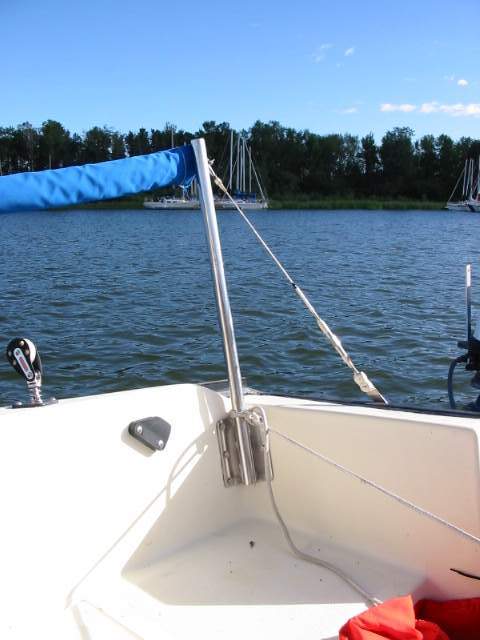
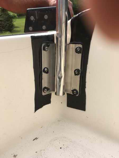
To
solve the problem I
transformed the aft stanchion (forward end of cockpit, 18" tall, 1" OD) into a lifeline gate by bracing the forward side
with a SS rod angled into the deck. The angle brace
supports the stanchion, relieving the mounting plate of stress when the gate
is open. The gate being the space between the
aft stanchion and the
pushpit. The braces were
welded to the stanchions, something I now regret. While they work
very well, attaching them with
a bracket equipped with set screws would have been so much easier for ongoing
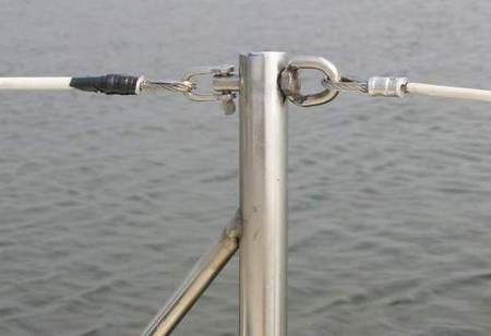
maintenance and winter storage. To terminate the forward life line
and maintain tension I fabricated a stainless fitting (bolt with half
ring welded to the head). The tension
in the forward line is adjusted with a turnbuckle at the pulpit.
 The tension of the gate line is adjusted with a
threaded Pelican hook latched to the metal loop welded at
the top of the pushpit. Always close this Pelican hook
facing outward to prevent accidental release by rubbing against it in
the cockpit. I quite often find these hooks closed the opposite
way and reverse them for safety. Its amazing how many sailors are
unaware of this simple act. For comfort and safety, the lifelines
gates are cushioned with foam tubing covered
with Acrilan or Sunbrella cloth as shown below. The tension of the gate line is adjusted with a
threaded Pelican hook latched to the metal loop welded at
the top of the pushpit. Always close this Pelican hook
facing outward to prevent accidental release by rubbing against it in
the cockpit. I quite often find these hooks closed the opposite
way and reverse them for safety. Its amazing how many sailors are
unaware of this simple act. For comfort and safety, the lifelines
gates are cushioned with foam tubing covered
with Acrilan or Sunbrella cloth as shown below.
Lifeline covered in vinyl can be a hazard in the long run due to hidden
corrosion. One day when you need it most, the line lets go.
Not good! So consider replacing them with Dyneema (Tech Tip B37) which is easy to splice. But you still need chafe protection at each stanchion hole in the form of a vinyl tube.
____________________________________
LIFELINE PADDING (1998) - Shortly after installing Panache's pushpit in 1998 I realized that leaning against a life line was not comfortable. So I added foam padding over the lines adjacent to the cockpit; (hollow foam water line insulating tube or a foam noodle covered with blue Sunbrella cloth). You can see one installed here and below. They work very well but with years of body pressure against them, the thinner life line wire eventually wore through the foam, leaving the sharp line against my back again. Aaarch, nothing lasts forever I guess!
(2022) I replaced the foam and this time inserted a vinyl tube inside the hollow foam with the life line run through the vinyl tube. The vinyl tube spreads the load over a wider area to keep the pads comfortable and make them last longer. The vinyl also bends when I lay the line on the deck. I also soaked the Sunbrella in hot water and scrubbed off the Lichens, which shows you how long I've had these pads. Maybe 34 years is forever after all.
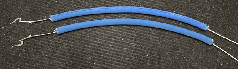
With Canada having converted to metric in 1975, the foam insulating tube today is a tad thicker than the previous imperial version which means it fills the Sunbrella tubes fully, resulting in a softer pad. Sometimes change is a good thing.
|
 Panache
has undergone many modifications to make life more comfortable
in the cockpit and safer on deck. The most challenging and rewarding was the conversion of the corner stanchions to a pushpit in 1998. Here's why:
Panache
has undergone many modifications to make life more comfortable
in the cockpit and safer on deck. The most challenging and rewarding was the conversion of the corner stanchions to a pushpit in 1998. Here's why:
 This split
pushpit shown belongs to Kevin from Kentucky. His design is
simpler and easier to fabricate than Panache's above. It is also easier to bolt in place. The fact that it is removable makes it very useful for winter storage. I like that.
This split
pushpit shown belongs to Kevin from Kentucky. His design is
simpler and easier to fabricate than Panache's above. It is also easier to bolt in place. The fact that it is removable makes it very useful for winter storage. I like that. 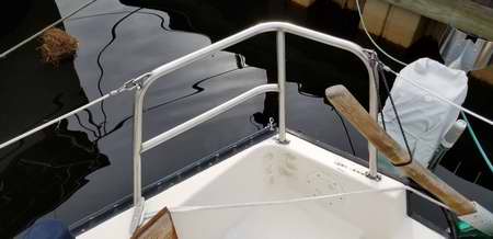
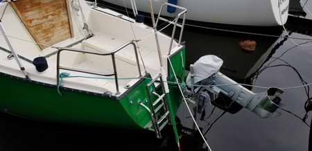 "I finally
completed my project using the last of the material in my garage. A local welder tacked it
together at a reasonable price. The polishing and
installation was fairly easy. Polishing compound with a
buffing wheel took most of the burn marks off. Then rubbing the SS with 00 steel wool and Comet cleanser
created the final finish. The pushpit adds a nice touch
to Liberty Call and is very functional. Glad I got it done."
"I finally
completed my project using the last of the material in my garage. A local welder tacked it
together at a reasonable price. The polishing and
installation was fairly easy. Polishing compound with a
buffing wheel took most of the burn marks off. Then rubbing the SS with 00 steel wool and Comet cleanser
created the final finish. The pushpit adds a nice touch
to Liberty Call and is very functional. Glad I got it done."