| SJ23 Tech Tip B30, (Issued 2016-08-02) Bill Ward | |||
|
Rudder, Make a Rudder Head & Blade. |
|||
|
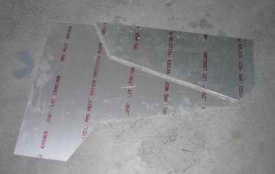
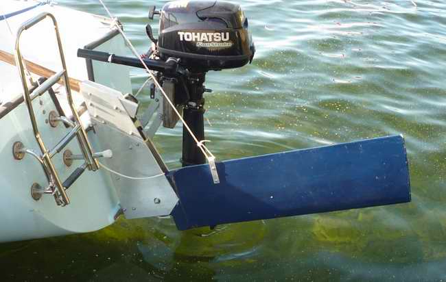
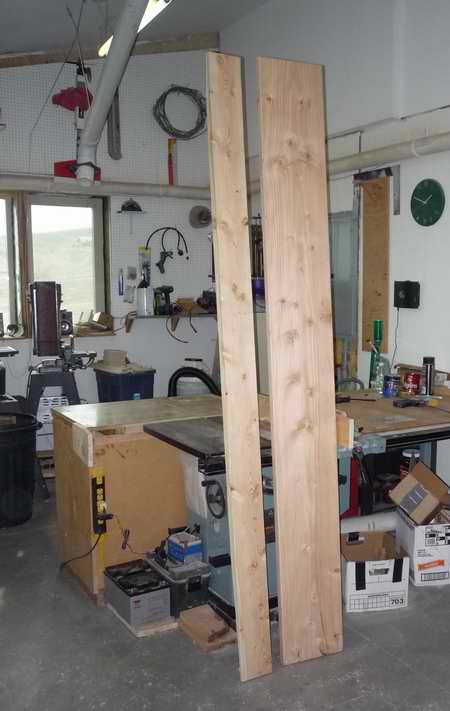
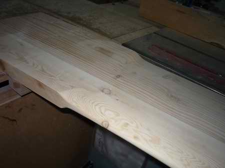
When I bought Knotless II she came with a lovely fixed rudder attached to the transom. I’m not sure the reason for having a fixed rudder on a boat with a swing keel, but I was pretty sure that if I floated into shallow water and bounced the keel over something on the bottom, bad things would happen to the rudder, the transom, or both. So, a kick up rudder was in order. Using the information in Tech Tips B09 and B10 I went to work in the Fall of 2015 to make a rudder that would tip up automatically when (not if) I entered shallow water unexpectedly. It turned out to be a pretty major undertaking but was both enjoyable during construction and satisfying now that I’m sailing with the new rudder. I started with a dry (2x14)" about 6' long, straight grain without run out and tight knots (no pun intended). There are no (2x14)" boards available where I live in Northern Idaho so I trimmed and glued together a (2x6)" and a (2x10)". After the epoxy cured I hogged out the basic shape of the foil on my table saw. My adjustable dado blade was set to about ½" wide and angled to about 70 for the trailing part of the foil. I guestimated the angle for the leading edge of the foil that is roughly based on the NADA 0020 shape.
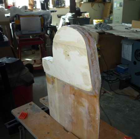
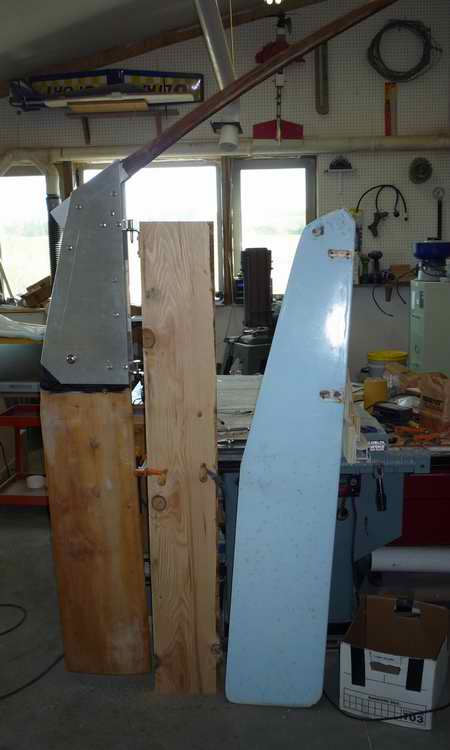
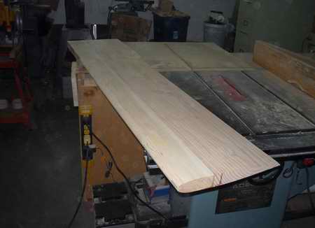
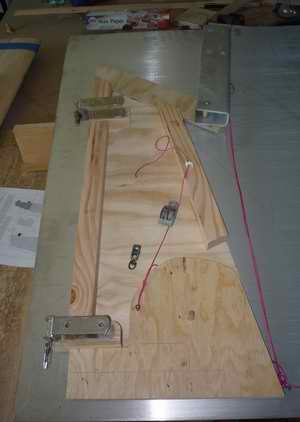
This picture shows the foil shape on the bottom of the blade. The top of the blade was left square to fit inside the rudder head assembly. I had to mark the rip fence and start and stop the cuts by lifting the board off the table saw blade on one side and starting the cut in from the end on the other side - the same technique used for a blind rabbet. I cut one side, turned the board over, and cut the other side for the same blade setting. Then I adjusted the rip fence and blade for the next pass. Yes, I DID make a practice foil before starting on the full size blade! Notice that the edges were left at full thickness to keep the plank level on the table saw. Once the foil was roughed out on the table saw I trimmed the edges and used a belt sander to finish shaping the foil smooth and formed the transition from the foil to the top of the blade that fits inside the head assembly. With the blade mostly formed, I started on the head assembly. Since the sides of the head are ¼" thick aluminum they are difficult to cut. I wanted them to fit and be symmetrical. For that reason I started with a plywood mockup shown below.
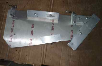
I also included the rudder pull down system from Tech Tip B10 and my own system for raising the rudder without using the lake bottom to start moving it up! More on that later. Once I was satisfied with the basic layout and shape of the rudder head, in plywood, I started working on the aluminum parts. I quickly learned that I have a wood working shop, NOT a metal working shop. Since, I really don’t have good equipment for cutting and shaping aluminum plate and tube, I made due with a combination of a right angle grinder, a reciprocating saw, and a belt sander to smooth the cut edges.
I used 1.25" spacers inside the pintles which allowed me to reuse the original pintles from the fixed blade. To bring the pintle to the required 2" width I used sections of ¼" plate for additional shims outside the pintle.
All fasteners are stainless through bolts with washers and nylock nuts.
Once I was satisfied with the rudder head, I shaped the top of the blade. This is where using 2" spacers between the side plates became an issue. Since a (2xX)'' piece of lumber is really only 1.5" thick, I had to add some plywood shims to the top of the blade. I glued them on with epoxy, then filled the gaps and edges with epoxy paste thickened with a filler. Because I was going to cover the entire blade in epoxy glass, I made the shimmed up head a bit thinner than the 2" gap between the aluminum plates. I used West System epoxies and fillers, throughout the project.
The entire blade was then coated with fibreglass saturated in epoxy with most of the wear areas doubled up for extra wear resistance (primarily the leading edge on the bottom of the blade — right where rocks will, someday, find the rudder!). I also had to add a couple of extra layers of glass cloth to the top of the blade to get a proper fit in the 2" space in the aluminum head. It was trial and error to get the thickness of the blade right and involved extra layers of glass and lots of sanding.
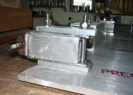
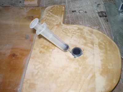
If you look carefully, you’ll notice the hole for the hinge pin is a lot bigger than the ½" suggested pin size. Not being satisfied with the having the ½" stainless bolt used for a hinge pin rubbing on the inner surface of the PVC nipple, I used two bronze bushings to make the slip surface. The inner bushing has an ID of ½" to fit the pin. The outer bushing has an OD that just fits the PVC nipple. The inner bushing fits properly in the outer bushing to make a nice fitting bearing surface. To prevent the outer bushing from slipping inside the PVC nipple, which would have been no better than the pin slipping, I scored the outside of the outer bushing and epoxied it into the hole in the nipple. Using bronze bushings is probably way overkill, but it does make for smooth movement of the blade.
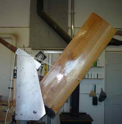
Since it’s a kick up rudder, it is appropriate to show it kicked up! Notice that it goes well above horizontal so it is out of the water when raised.
At this point I removed the blade and applied 3 coats of blue marine polyurethane paint to match the hull.
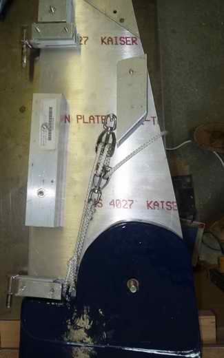
While the aluminum head was apart I worked out the pulley system for lowering the blade into the water. It is very easy to lower the blade while on the water! To hold the blade down I used a Clamcleat® CL257 mini auto-releasing rope cleat fastened to the outside of the spacer near the upper pulley. While I haven’t hit anything, yet, to test the release action of the cleat it seems to release fine when tested by hand on the trailer. The extra length of line used for lowering the rudder is tied to the backstay, just in case the rudder decides to jump out of the gudgeons when in use! To hold the rudder in the raised position I bent a piece of aluminum strap and fastened it to the trailing edge of the blade. Notice the tiller extends beyond the rudder head and has a cleat on it. I didn’t know how easy it would be to pull the rudder up from the fully lowered position so I use the back end of the tiller as a lever: raise the tiller to vertical, place the line from the strap in the cleat, lower the tiller. The rudder blade pulls far enough from straight down to then float to the surface. It and moves far enough to be lifted by hand, if on the trailer. As it turns out, on the water it’s pretty easy to just pull the line and raise the rudder since it floats quite well.
Knotless II came with a boom jack on the back stay. Since I installed a topping lift, the boom jack isn’t used much anymore. It does, however, provide an excellent place to fasten the rudder lifting line to hold the blade up. Of course, the strap and lift line, when sailing, are in the water. If I was a “real” sailor I’d take exception to the drag they cause and do something else. But it works for me and is easy to use! I’ve sailed several times with the new rudder and am quite pleased with it! I wish it weren’t so heavy, but I’m not sure how to lessen the weight of the aluminum head. Wood spacers would have been a bit lighter and could have been sized correctly to minimize the use of shims, making the assembly a bit easier and lighter. I think the difference is negligible. The aluminum spacers are forever while wood spacers would have swelled with humidity and/or need replacing. Once it’s on the boat weight doesn’t really matter, anyway.
Bill Ward |
|||
|
Return to Tech Tip Index. . . . . . . . . . . . . . . Have a Question? |
|||
 At long last
this rudder project is
complete. It was an interesting one that might help
someone avoid the dreaded hard grounding with a fixed rudder.
At long last
this rudder project is
complete. It was an interesting one that might help
someone avoid the dreaded hard grounding with a fixed rudder. 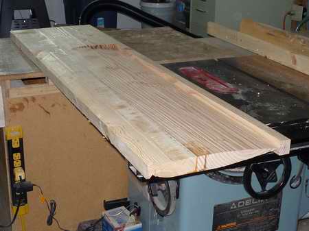
 T
T