| SJ23 Tech Tip E11, (Updated 2024-11-21) Bob Schimmel | |||||||||||||||||||||
|
LED Lights on an SJ23 -
Minimal Power Consumption. |
|||||||||||||||||||||
|
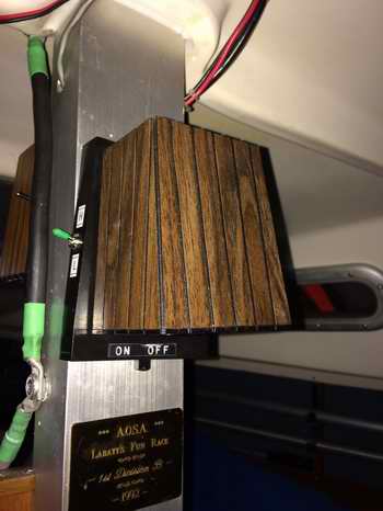
CABIN
LIGHTS - The factory faux wood light fixtures
installed at the top of the SJ23 compression post are a bit wanting for
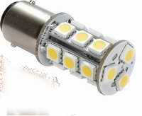
illuminating the cabin with the incandescent bulb. The fixture is temperature rated for an 1141 incandescent bulb
(automotive 12V
clearance bulb or park light) that has
a single contact base (bayonet pins in line). It can be
replaced with an
equivalent LED bulb
(1141 or 1156) to reduce power consumption from 1500MA to 200MA and
improve the quality of the light.
Since the daylight
version of an 1156 LED is
brighter than an 1141, you may find it desirable to
reduce the light intensity with
a power
dropping resistor (80Ω, 1/2W)
operated by a switch installed somewhere on the base of the fixture. This
further reduces the current from 200MA to 50MA.
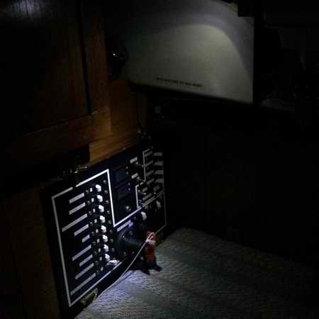
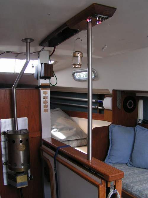
Shown below is the power panel illuminated at night and a view into Panache's cabin as I approached from the dock. The anchor light is glowing over the cockpit. This is the first time I've seen the cabin illuminated from the outside and the cockpit bathed in light. A nice warm, welcoming feeling.
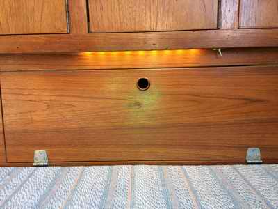
Other useful locations for LED lighting would be
inside a locker
to find stuff at night, under the table to light the
cabin sole, under the companionway to light the steps and in the forward
berth for reading. Maybe later. In the mean time enjoy the light.
TOP
The purpose of these lights is to illuminate the cabin without affecting my night vision. I was doing a lot of night sailing in 2005 and wanted low power lighting. To that end these lights are a success and it is oh so sweet to have them. However, you might want to operate the LEDS at full brightness and install a dimmer switch to fine tune the brightness to your night vision. Everyone's night vision needs are different. The LEDs are NOT adequate for reading which is why I added the low intensity switch to the pedestal lights and the indirect lighting to the ceiling. But I'm also considering a light under the table for those times when I need it slightly brighter without glare after waking up in the middle of the night. It creates a more indirect lighting effect in the cabin. I also discovered how important it is to operate a low intensity red light in the cabin while sailing at night. It gives you something to anchor to and helps to orient yourself in the cabin. Both are equally important when you wake up in the middle of the night. Yes it contributes to your night time power drain but it saves body injury for negotiating your way through a strange place. PS: LED
lighting was in its infancy in 2005 at the time of this installation. I
bought a handful of the original dual in line pin high intensity white LEDs from a local
electronics wholesaler. This was only a few years before white LEDs were
available. Today's LEDs are far more energy efficient. I
tested red and white LEDs in their dark room and was surprised at how well
they illuminate and how well I could see with this quality of light.
There is no shadow to the edge of the light. The brightness simply
fades smoothly to darkness at the edge of the beam so the human eye doesn't have to deal with the
sharp contrast there; a phenomena that is typical with
a reflector behind a filament bulb. Since I wanted good night
vision, to which I might occasionally add soft white light, I chose the
medium intensity LEDs. See Note 1 at end.
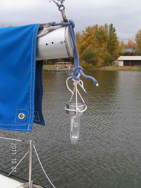
NOTE to ALL: A solar garden light sucks as an anchor light since it is barely visible at
100' (33M), doesn't shine longer than 6 hours
and for these reasons does NOT meet Collision Regulations.
Stay up one night and you'll see for yourself. This means it can't shine through
a night
unless you live North of 600 where a summer night is barely
perceptible, having only a few hours of dusk. Use
an approved anchor light in the presence of other boats, especially
commercial traffic. Although in a pinch a garden light is better than
leaving an
anchored boat dark. TOP
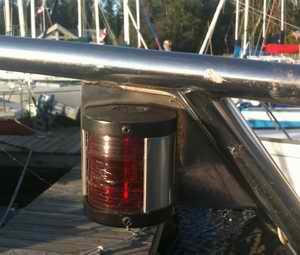
Years ago I was reluctant to exchange Panache's incandescent bulbs to LEDs since it was expensive to convert them and difficult to justify for the few times I motored or sailed at night. Late in the evening (23:00 at the height of summer) I usually motor to my mooring or an anchorage so the 2.7A draw of all my incandescent bulbs can be handled by the 6A generator in the outboard. But if the battery is also low the generator can barely charge it due to the extra load. When I do sail this late in the evening I usually have a >4KM visibility and I'm generally the only boat on the water, so no problem. However, If you live in the southern US where it gets dark much earlier, real quick, and you have to deal with commercial traffic, I would seriously consider LED bulbs. Three LED bulbs draw less power (approx 330MA) than three incandescent bulbs (2700MA). Using a flat cluster of warm white SMDs is optimum since it is the same colour temperature (3500 Kelvin) as an incandescent bulb. Only the red or green frequencies pass through the corresponding lens and the rest are blocked, which also applies to an incandescent bulb. While the blocked light is waste, the LED cluster uses only (100MA) current compared to the incandescent bulb (900MA). Therefore an LED is a huge improvement over an incandescent bulb as the current and heat are greatly reduced while improving light intensity.
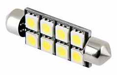
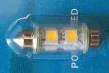
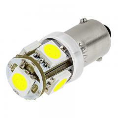
So for Panache's navigation lights (Tech Tip B26) I chose to install a 578 festoon white directional bulb equipped with 8 surface mount diodes (SMD) purchased from SuperBrightLEDs. A friend chose to install a USCG certified white omni directional bulb (part # unknown) on his boat. I'll hold off naming his boat! The brighter LEDs on the certified bulb are installed around a round core. Since we have the same fixtures it was a perfect opportunity to compare a directional versus an omni directional bulb. The results are as follows:
Measuring Light Intensity -
A lumen meter measures light power using all colours of the visible spectrum. It is an accurate way to measure white light but can be deceptive when measuring a single wavelength (frequency) LED. Because multiple wavelengths create white light and a coloured LED has a single wavelength, the LED will show a lower lumen reading. However, the coloured LED will appear to the eye to be equally as bright as a white bulb.
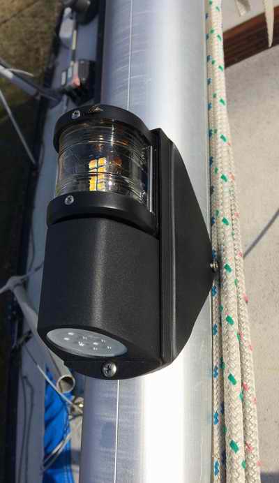
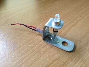
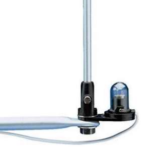
ROAD GRIT - The bottom (deck light portion) of a Victory AAA steaming/deck light is open and points forward when traveling down the road with the mast horizontal. As such it can scoop road grit and rain water. To avoid this, smear grease in the socket to prevent corrosion and tape the bottom of the fixture closed. Fortunately the bulb cluster is sealed at the bottom (shown at right) and won't have this problem but I will still tape it to protect the surface of the bulb if I'm traveling a long distance. VISIBILITY - One should not forget how effective a mast light can be to illuminate the deck for night work or to make yourself temporarily more visible to another vessel. Its not regulation of course but if it looks like the other vessel is maintaining a collision course to you, I'd switch on the deck light. TOP
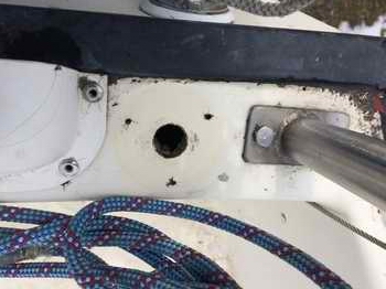
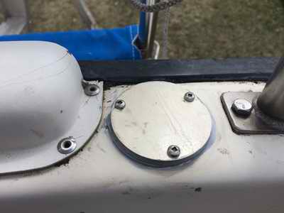
NOTE - To store this light assembly for trailering, I loosen the nuts on the cockpit side of the clamps, remove the assembly, then screws the parts together so I don't loose anything and store the assembly in the cabin for winter. It rides nicely on top of my galley cabinet. The factory stern light was removed from the transom and the hole capped with a colour matching disk of fibreglass as it is too difficult to do an epoxy and colour matching gel coat repair in this tight space. Besides, this way I can always reinstall the light if I have to. I can finally place my foot here!
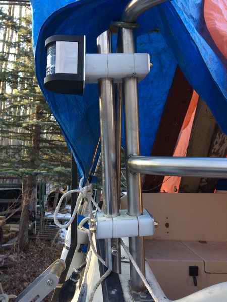
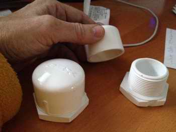
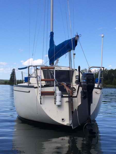
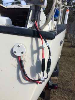
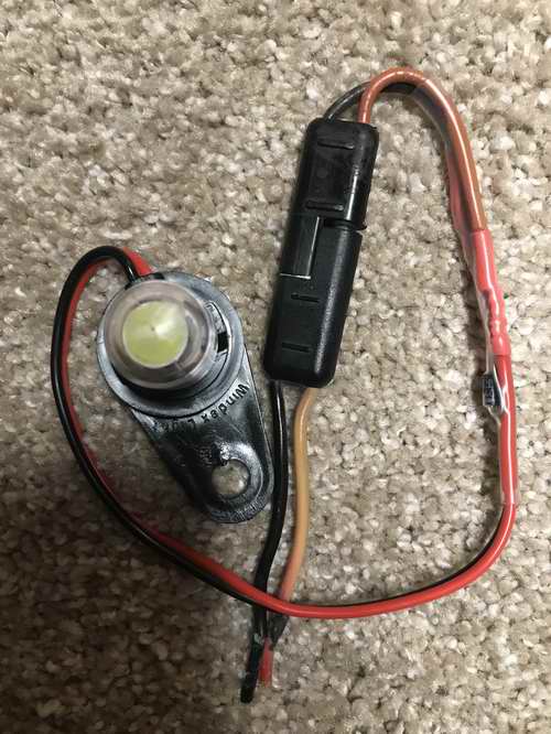
ANCHOR LIGHT (2016) - An incandescent anchor light can draw a lot of power from a battery since it operates for a LONG time without a means to charge the battery. This is typical in southern US latitudes or during a shoulder season in northern US or Canadian latitudes. To reduce power consumption use an LED light and operate it automatically with a darkness switch, unless you enjoy getting out of bed to shut it off with the rising sun! I struggled with where to install it; at the mast head (regulation height as of 1850) or lower to the water (in line of sight to power boaters). Ultimately I chose a low light that is directly in the line of sight to the local "cowboy boaters" who motor around during their romantic evenings, with anything but navigation on their mind. These people never think about floating hazards and are oblivious to collision regulations. To them the lake is an empty "parking lot" to tool around on. My other reason for not installing the light on the mast head is that it often blends in with the stars or shore background lights, making it more difficult to see. Plus, the local power boaters NEVER look up. For these reasons I installed a bright 3600 anchor light installed 8' above the surface. It is so effective that the cowboy boaters now give Panache a wide berth when on her mooring and other sail boats used the light as a beacon to enter the bay. A lot can be said for operating another light at the bow to show hull length or a cockpit light to increase the visibility. Cabin lights don't show very well through the windows.
I fabricated this anchor light in 2016 using 8
high intensity dual in line pin (DIP) LEDs pointed horizontally and equipped it with a darkness
switch. The switch consists of a light dependant resistor (LDR) mounted on top,
pointed to the sky. This anchor light looks similar to
a Bébi
light that was manufactured in Fiji but the electronics is my design. "Its too bad Bébi
was forced out of business. I was eyeing their design for a long time
and buying one would have been a whole lot simpler
than making one! It isn't till you fabricate one of these that you
really appreciate their design. Oh well I had bags of LEDs and
nothing but time on my hands during the winter." CASE ASSEMBLY - The PVC potable water components are available at a home improvement or plumbing shop. For a stiff mast I selected the 1/2" ID, thick wall tubing and removed the outside printing with fine sandpaper so it looks presentable mounted on the boat. For the LED housing at the top I used a 2" OD end cap with a matching size base. All 3 fit together quite nicely. Cut off all but 1/4" of the threaded portion of the base so the remaining thread functions as a lip to support the circuit board. Drill a hole through the base to fit the mast to. Make sure it fits snug over the tube and is held with epoxy. Bevel the top inside circumference of the mast (tube) to a smooth ridge for the power wires that will go down. Drill some 1/8" ventilation holes through the base. The cap is clamped to the base with a threaded brass rod down the center. Because it goes through the circuit board, the top of the rod is insulated with heat shrink. Since the light is permanently mounted on the transom the 1/8" rod extends through the top as a bird spike. Last thing I need is poop covering the light sensor. Click here for case assembly.
CIRCUIT BOARD ASSEMBLY - Solder all components to the Veroboard and wire the LEDs
using ~3" long #24 stranded wire. The insulation must cover the wires
completely for final assembly. Solder the
input power cable to the bottom of
the Veroboard since it is the natural direction of the wires going down the hollow PVC staff.
The power cord
exits out the bottom to a plug. Click here to see my
schematic, Veroboard
component layout (X denotes where to
"open" the PCB run with a drill bit) the
run side,
& the
component side of the 1.5" OD circular
board.
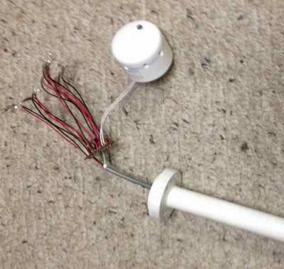
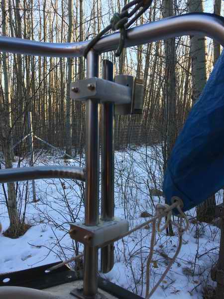
FINAL ASSEMBLY - Form the LED wires together into a bundle and then fan each LED outward like a flower as shown on right. I used needle nose pliers to point the LEDs outward. Line up each LED with a hole drilled through the side of the cap. Smear silicon sealant in each hole and push the LED in to collar depth. Remove excess sealant from the exposed outside of each LED. Once the sealant has cured (24hrs) form the bundle of wires into a spiral coil so it can be pushed (screw fashion) inside the cap as it goes down over the rod and onto the base. Do this with the power on so you can detect a problem during assembly. This is the test to confirm everything is well secured and insulated. Once the cap is down on the base and all 8 LEDs are still lit, you are good to seal the unit. Spread a thin bead of silicon sealant around the base and snug up the nut on top of the rod. The only way to service the electronics is to release the nut and cut the sealant with a razor knife. Relax, it should last a lifetime. INSTALLATION ON SJ23 - Panache's anchor light is mounted on top of a 44" mast (3/4" PVC tube) positioned where there is a 3600 clear visibility above the cabin height and below the boom. The staff is supported inside a SS tube clamped to the aft side of a pushpit post where it is out of the way. The UHMW clamps shown below are amazingly strong. The PVC staff is heat bent so the upper portion is vertical for flat illumination across the water. A small screw through the bottom of both tubes locks the staff in place; up/down and axially. It is quite easy to remove the entire assembly for road travel but I have occasionally left it on with no problem. You should be able to adapt this technique to your boat.
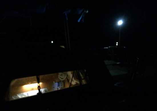
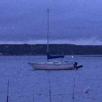
The anchor light is even more visible over water. The night photo at left was taken about half way through dusk with a digital camera. Shortly afterwards I drove to the far shore shown in the photo and I could see my light with the naked eye. That shore is about 1 KM away. This is good performance for only 30 MA of current. The light from a DIP style LED radiates in a 200 beam, so it is very bright when you are in line with the beam. At right is a photo I took without a flash to show just how well the cockpit is illuminated at night. I think I could actually read by this light. NOTE - The two night photos shown here are a bit deceiving because a digital camera can penetrate darkness and rain better than an analogue camera. I don't know why but it can create some cool effects. (Repair 2021) - I discovered the anchor light drew low power continuously and it no longer switched on at night as the LDR had lost its acrylic cap due to UV damage. So I scrounged a new LDR and window from a surplus wall mounted night light. The plastic window was epoxied into the top of the cap to protect the LDR from UV and I replaced the dead LDR. This was way easier than buying the separate components. I also added a threaded brass rod (bird spike) through the center of the light to clamp the cap down to the base. Repair (2024) - Two LEDs have gone dead after 8 years of operation. That's pretty good considering that I've done only one repair to the light during that time. After opening the case I discovered a bit of corrosion on the circuit board, indicating the dome leaked and the conformal coating failed. Although, dew has a way of penetrating things like nothing else. Testing confirmed one of the LED power leads detached due to the corrosion. After cleaning the corrosion I soldered the lead back on and all LEDs operated correctly. Then I sprayed the board with 2 coats of conformal coating and added a smear of silicon sealant to protect the runs from dew. The dome window through which the lDR detects light was sealed as was the bird spike. Its all good to go again. TOP
INSTRUMENT LIGHT
- Is can be quite an improvement to replace a tiny incandescent instrument
bulb with an LED. I've modified all my instruments to LED lighting
to improve the visibility, reduce the glare with the softer light and reduce power consumption. In most
cases this change is not difficult to do but if you can buy a plug in replacement it is
usually the best. TOP
To protect the LED from an electrical surge I added a diode (1N4007) across the power leads, imbedding it in the fixture wiring. (Delicate work of this nature should NOT be done at the mast head. It is best to add this diode & connector to the wiring harness on a workbench, then install the assembly at the mast head).
NOTE - The LED/diode combination does not radiate RF to the adjacent VHF antenna.
Similarly an LED that is exposed to the atmosphere (Windex light) can burn out due to an induced aerial charge (EMP) associated with lightning. I relearned the lesson of transient voltage protection the expensive way during my installation of the cabin ceiling LEDs and cooling fan. They happened to be wired to the same circuit. In 2004 there were lots of relatively inexpensive electronic "toys" with LEDs available that would suggest that LEDs were cheap. This was correct for the red LEDs, but certainly not for the high intensity white LEDS. They cost $5.00 Ca each at the time. I bought mine at a local electronics wholesale where six red and six white (low intensity) LEDS cost $20.00 Ca. By 2009 the costs were down considerably.
The simple solution for both problems is to connect a transient voltage suppressing diode (P6KE) or a
low power diode (1N4007) across the
fan motor or relay coil to
short out the voltage spike right at the source.
A transient diode can switch on much quicker than a low power diode,
making it the superior device. Its
best to connect the diode as electrically close as possible to the source to prevent the spike from propagating across the circuit.
Connect the
cathode (striped end of the diode)
to + and the anode to - (negative).
The normal power flow
to the LED is not affected and the diode does not conduct.
The diode conducts only for the reverse polarity voltage pulse impressed on
the LED, effectively shorting
it out to protect the LED and anything else connected. Diodes are
inexpensive and provide effective protection. TOP |
|||||||||||||||||||||
|
IMPORTANT NOTE 1: Because an LED emits light in a very narrow frequency band, you will likely perceive the LED as slightly dimmer than a broad spectrum tungsten filament bulb. The light receptors in your eyes detect less power to a narrow spectrum LED light than to a broad spectrum filament light. Instrument lights can be blue or green (instead of red) yet not interfere with night vision as long as the intensity is kept low. This makes it easier to see the tiny graduation on a meter scale or to read fine text and is what retains your night vision, making an LED so beneficial. A dimmer can be made from a potentiometer or a variable regulator. Here are some facts about human eyes and light;
|
|||||||||||||||||||||
|
Return to Tech Tip Index. . . . . . . . . . . . . . . Have a Question? |
|||||||||||||||||||||
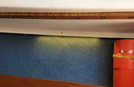
 Even
with the brighter LED bulb in the pedestal fixture I considered the edge of the cabin
to be too dark.
For this reason I installed
Even
with the brighter LED bulb in the pedestal fixture I considered the edge of the cabin
to be too dark.
For this reason I installed 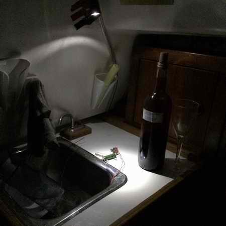

 VICTORY
AAA FIXTURE
VICTORY
AAA FIXTURE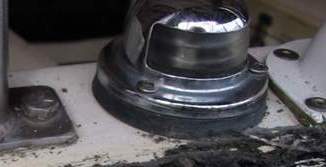
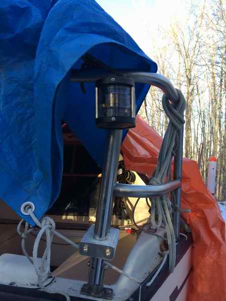
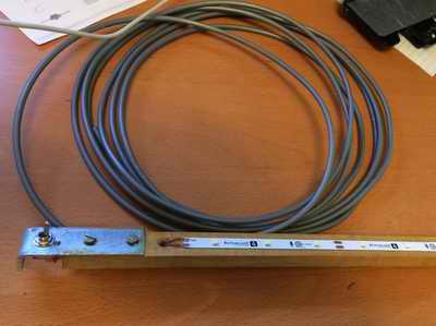
 To
test the light I installed it on Panache while she was on her trailer
parked in the bush. I can report that it is easy to see
from 300' away, which is good considering there was no snow at the time
to reflect light. I built a second light for my buddy and he reported that in
total darkness the light cast his shadow against the house 30' away.
This is good performance for only 22 MA of current on his light.
To
test the light I installed it on Panache while she was on her trailer
parked in the bush. I can report that it is easy to see
from 300' away, which is good considering there was no snow at the time
to reflect light. I built a second light for my buddy and he reported that in
total darkness the light cast his shadow against the house 30' away.
This is good performance for only 22 MA of current on his light. 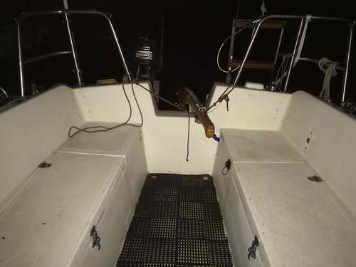

 4
-
4
- 