| SJ23 Tech Tip E13, (Updated 2018-12-08 Under Construction) Bob Schimmel | |||||||||||||||||
|
Connect
a GPS to an Autopilot or VHF. VHF-DSC Radio, GPS, Waypoints, Auto Pilot, Data Wiring, Panache Installation, About NMEA, Plotter |
|||||||||||||||||
|
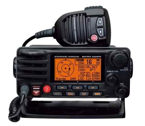
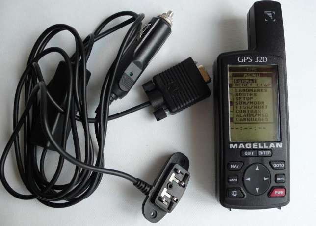
NOTE: In 2016 I installed a Standard Horizon Explorer GX1700 VHF-DSC radio. It is equipped with an internal GPS receiver that necessitated a change of the NMEA wiring I had with a Uniden VHF that died after only 2 years of use. The replacement Standard Horizon is much easier to operate. The amount of navigational data on some boats can be downright phenomenal, what with multiple programmable displays. Most manufactures of marine electronics sell a family of interconnected instruments that are designed to "talk" to each other for enhanced operation. This integrated operation generally requires a "data hub" with proprietary protocol to direct the data to/from each instrument, all with perfect signal quality for error free data transmission. The expense of this class of instrumentation is hardly feasible on the average SJ23 used for weekend sailing, but if you have deep pockets and want this degree of sophistication then by all means fill your boots. I still want some of the enhanced operation so opted for a simpler configuration, with the lowest possible power consumption. The correct data wiring is still required though, so don't go cheap by using the wrong cable. On Panache I have three navigational instruments; a Magellan GPS320 navigator, a Standard Horizon Explorer GX1700W VHF-DSC radio (Digital Selective Calling) and a Raymarine ST2000+ Tiller Pilot. I also have a Signet analogue knot meter, a Ritchie compass and a Hawkeye depth sounder but they don't count in my wiring scenario. I wired the three together for the enhanced features and convenience of operation. Given compatibility, these basic instruments can be swapped for other manufactures. "An autopilot equipped with NMEA tracking capability is a good choice for an SJ23. Being able to automatically follow a route programmed in a GPS navigator, not just a heading selected in the autopilot, will make life much easier for a solo sailor. This is especially true if you traverse a long stretch of cross current or side wind that will set you sideways to a dangerous area." Hal Mueller. THE CONCEPT - My idea was to hardwire the NMEA leads from my GPS navigator directly to my Tiller Pilot so it could follow a track as Hal suggests. The GPS receiver will source the following NMEA data sentences; Cross Track Error, Bearing to Waypoint, Distance to Waypoint, and Waypoint Number at 4800 baud async. I can view the GPS navigator screens to confirm I'm on track while cruising to a waypoint or along a route. Add an iPad with Navionics software and you have the overall picture. "A sailing buddy demonstrated a perfect use of this technology when he decided to motor back to his mooring after the midnight fireworks. This was during one of those rare pitch black, clear nights up here when, if you stare long enough into the dark, you can actually see. It is the perfect clarity for fireworks by the way. By selecting a route on his navigator he knew the boat would stay on a safe course to his mooring. As he passed by each waypoint, and the very important cardinal buoy, he heard the expected warning beeps, keeping him oriented. It should be noted that there is no floating debris and only two well lit Cardinal buoys to mark hazards on this lake. He knows the lake very well and we both keep a chart on board for back up use. The route took his boat right to his mooring ball 8KMs away. He updated his progress to me with text messages, keeping me in the loop! Pretty impressive when you know where you are but can't see more than 75' ahead." When my analogue VHF died I replaced it with a VHF-DSC radio equipped with an internal GPS receiver. While a VHF-DSC radio has lots of useful capabilities, it wasn't my first choice because the nearest Coast Guard station for is 1,200 KMs away! Duh, I would never be in RF range to send a distress call to them so why buy one! "But I have a certain old sailing friend who convinced me to move up to current technology in the hopes that my influence would entice other "fossils" on the lake to start using their DSC functions; familiarity leading to proficiency of use. It's actually working, albeit slowly. We're also working out the "subtle details" of duplicating the Coast Guard function here for handling a distress call, which is no minor task this far inland." After studying the VHF manual my simple configuration had a possible alternate if it was wired correctly. The goal being a configuration that draws minimal power, to navigate with a bullet proof operation, so any crew can transmit a distress message with the push of the DISTRESS switch. You want simplicity & speed during an emergency. _________________________________________________________________
NOTES
EXTERNAL GPS ANTENNA - If your VHF-DSC is not equipped with an internal GPS receiver then an external navigator or active GPS antenna is your next best choice. An external GPS antenna works best if mounted on the transom since this spot has unobstructed visibility to the sky. But it should be installed as far away from the secondary VHF antenna as the received GPS signal is extremely weak, being 10dB below noise threshold. Your body does not affect signal strength as long as you don't cover the top of the antenna. If the sails are above the GPS they can also affect the signal strength. TOP _________________________________________________________________
Match the following configuration:
MANAGING GPS WAYPOINTS & ROUTES the EASY WAY- A PC equipped with a GPS management application like EasyGPS 6.11 (Win 7 or 10) is the only "civilized" way to manage the waypoints and routes for a GPS navigator. It is so much easier and quicker to use the PC keyboard than to trip your fingers on that tiny GPS keyboard. (For Linux or Apple operating systems try GPS Drive).
As a side note it is interesting to view my tracks over the course of a sailing season, now that I switch my GPS on every time I sail. Think you aren't a creature of habit? Its surprising how close my tracks are to each other. TOP _________________________________________________________________
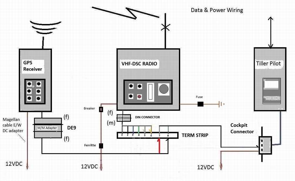
NMEA DATA WIRING -
The default NMEA data speed of most marine device is 4800 baud for which you can use
category 3 (Cat3) cable (voice grade, stranded, twisted pair).
Use the shortest length for minimum loss.
The block wiring diagram below looks amazingly simple but can be a
tad difficult to trouble shoot once installed. For this reason I connected and configured all the devices on a work
bench to confirm overall functionality, then installed it on the
boat with confidence. "I am not
going to be responsible for your grey hair!"
NOTES - Refer to power, audio and NMEA cabling table above.
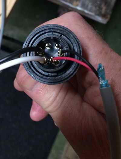
NMEA BENCH TESTING - This is the electrical connection to the Tiller Pilot for my bench testing of NMEA control. NMEA wires (BK-neg, WH-pos) on the left and DC power (BK-neg, RD-pos) on the right. The connector key is at the top. This allowed me to confirm the wiring configuration and various GPS options at home during the winter. My bench testing is now complete with the Tiller Pilot displaying the correct NMEA commands on the screen. While I'd love to say it works, I'll reserve my conclusion till Spring of 2019 when I will run it through a sea trial to confirm operation. Can't wait for that. TOP
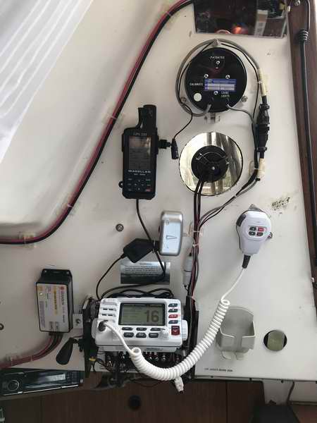
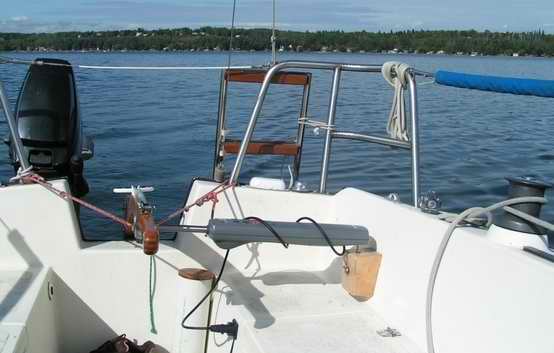
PANACHE INSTALLATION - Shown here is the completed Standard Horizon GX1700 installation. The coiled GPS cable on top of the radio allows me to extend the GPS to the cockpit. It's always nice to see a screen, tiny as it is, to navigate to a waypoint. The required DSC & channel 16 warning labels are strategically placed above the radio. The terminal strip (nickel plated) is visible just below the radio. Each connection on the terminal strip is labeled to facilitate repair. I hate having to reverse engineer one of my installations especially when labeling is so easy at installation time. My installer background! Using this hardware makes the job of navigating easier when traversing tricky shallow water, going around an island or motoring to a location over the horizon. It frees me up from the tedious task of steering so I can complete chores on board while maintaining a lookout. Later I will add an iPad Mini 4G equipped with internal GPS and mapping software as a substitute to a chart plotter. While a chart plotter doesn't give you visibility in fog or the dark it will help to keep you oriented, making it easier to deal with an issue around you. The screen resolution of an iPad is very good and it is so easy to zoom in/out with the touch screen. To make an iPad waterproof, tuck it inside an acrylic topped Pelican case. Alternatively if you use a laptop as a chart plotter, then wire the GPS NMEA data output +/- to the PC RXD data +/- input. Connect the laptop to boat battery for long term operation. Notice the tiny toggle switch on the aluminum mounting
plate at the top left of the
radio bracket. It operates the LED light to illuminate the power panel.
Up is permanent on and down is momentary on. |
|||||||||||||||||
|
NOTE on GPS COORDINATES - Just because your GPS
navigator shows
"GPS
Data OK" does not mean you should take the coordinates as gospel. It is
sometimes possible (although rare) for a GPS navigator to have a fix that is off
by some degrees.
In our case both navigators were off by 1500 meters with absolutely no
indication of a problem. I've experienced
this only once as my buddy and I floated near a
railroad trestle which is also under
a high tension line. Both navigators were off by the same amount
and changed at the same time as confirmed by a second trip into the
affected area. The fix was
to leave the area and power cycle both navigators. If you don't
power cycle the navigator, the coordinates will remain off till it is
power cycled.
This is the only place I have experienced this problem but other
people
tell me they have experienced it in several places. I now
regularly compare the GPS coordinates against a chart (another good
reason to carry a chart). By the
way, the aircraft version of a GPS navigator is protected against this
by checking itself. This is the basic difference between a
commercial and a personal unit. Problem is, you
can't afford the aircraft version! TOP |
|||||||||||||||||
|
CHART PLOTTER
(PC or
iPad)
- Most lake sailors don't need
a chart plotter to see where they are. The shore close by
makes it somewhat self evident! But every once in a while
somebody goes off the beaten path and then a chart plotter comes in real
handy to get you unlost! Hopefully you can figure out how to
get back!
(Laptop equipped with mapping software) - While a laptop equipped with mapping software is hardly practical in the cockpit as a navigation instrument, in a pinch it can be used as a chart plotter at the navigation station. Good luck tying it down for sailing. Its also more difficult to operate from the boat battery. (iPad) - I prefer an iPad equipped with Navionics
in the cockpit, especially if the pad is in a water tight case.
However, it can shut down with high temperature so be careful exposing it to the sun. The details that Navionics can display are
excellent. The really nice
feature is that users are encouraged to submit
corrections to update or correct the map. Two of us are doing this at our
lake and the accuracy has really improved over this past summer.
Everybody benefits. The application is free, its the map
you have to pay for. It is real efficient to charge or operate
an iPad from the boat
battery using a 12V USB adapter. The 2A version will get it
running that much quicker and is more dependable than the el-cheapo
crap purchased at a convenience store. (Just because the iPad
battery charge indicator
shows 100% it does not mean the battery is full. When the
charging icon disappears, then the battery is fully charged). TOP |
|||||||||||||||||
|
ABOUT NMEA DATA - NMEA (National Marine Electronic Association)
data is a communications protocol for marine navigation devices.
The data consists of sentences that are transmitted sequentially
to provide essential machine commands and position fix data
necessary for electronic navigation.
A subsequent
sentence may supply new data but many of them are repeated and
therefore result in no change to the receiving device. Each
device watches for
a sentence that applies to itself and ignores the rest.
Effective and simple. It is possible to view the NMEA (ASCII data) transmitted from a GPS navigator by monitoring it with HyperTerminal, a software communications application that comes with Windows XP & earlier. This is a handy testing technique to determine if the GPS navigator is sending NMEA data. If HyperTerminal can log the data then you can also build a history of the entire session by saving it in a file. I used to monitor async data with a "dumb" async terminal as a test technique in the late 1970s. Today you have to monitor async data using HyperTerminal. There is little specific information about NMEA wiring. The physical interface is actually EIA422 (resembles RS232) with isolated inputs and outputs. The NMEA standard uses a simple ASCII data format; 4800 baud asynchronous, 8 data bits, 1 stop bit, no parity, serial communications protocol. A talker (sending device) can have a unidirectional conversation with a nearly unlimited number of listener (receiving devices). The majority of the data payload is in the form of "sentences" that contain machine commands. The only readable sentences are coordinates. If the PC is equipped with USB ports then it will require a USB to serial adapter. While I have not tested the interface connection to the boat network, it will require a serial (COM) port with a null modem adapter to satisfy the EIA handshake protocol. If a bulkhead DE9 connector is incorporated in the boat network it would make it convenient to connect the PC to. You might learn some interesting things about NMEA data protocol while a GPS navigator talks to a Tiller Pilot and plots your track on the PC screen. NOTE About Garmin GPS Navigator - A Garmin GPS navigator converts lat/long coordinates
using the datum
selected by the user when sending NMEA data. This is indicated in the
proprietary PGRM sentence that a program uses for map datum that is not a NMEA standard. Be sure to set your Garmin navigator
datum to WGS84 when communicating to a NMEA capable device. There
might be an equivalent setting for Magellan and other GPS navigators.
|
|||||||||||||||||
IMPORTANT - All the "toys" available on a boat aren't
necessary on a lake with visibility to shore, but there is something inherently
comfortable in telling it to take you to a destination and unfailingly
getting beeped as you pass each waypoint. The use of this technology does
not excuse a vessel operator from maintaining a vigilant lookout or
using a printed chart.
|
|||||||||||||||||
|
Return to Tech Tip Index. . . . . . . . . . . . . . . Have a Question? |
|||||||||||||||||
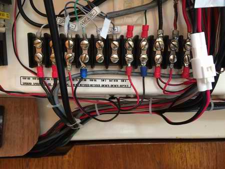 VHF TERMINAL
STRIP - At right is a close up view of the audio, NMEA data and power
wiring on the terminal strip installed below the
VHF-DSC radio. The DE9F connectors to the left are for the external GPS NMEA data leads
that go directly to pins 7&8.
There is a M/M gender bender between the two. The DIN connector, barely visible behind the heat sink, is for the VHF
radio NMEA data leads 3&4 5&6.
For clarity the co-ax cable to the antenna is not connected. These connectors, along with the white power connector, make it quick and easy to remove the
electronics
for winter storage in the warmth of my humble abode. My
original aluminum mounting bracket around the VHF continues to house the radio and
protect the terminal strip wiring.
VHF TERMINAL
STRIP - At right is a close up view of the audio, NMEA data and power
wiring on the terminal strip installed below the
VHF-DSC radio. The DE9F connectors to the left are for the external GPS NMEA data leads
that go directly to pins 7&8.
There is a M/M gender bender between the two. The DIN connector, barely visible behind the heat sink, is for the VHF
radio NMEA data leads 3&4 5&6.
For clarity the co-ax cable to the antenna is not connected. These connectors, along with the white power connector, make it quick and easy to remove the
electronics
for winter storage in the warmth of my humble abode. My
original aluminum mounting bracket around the VHF continues to house the radio and
protect the terminal strip wiring.