|
SECTION 1 - DISTRIBUTE POWER
 BATTERY
LOCATION
- A liquid filled battery should be installed in a
water proof battery box with a battery blanket at the bottom to absorb all the electrolyte the battery can hold. The battery box must be
insulated so there is no chance the terminals can be electrically
shorted to something. The battery box must also be vented to the outside to
release any explosive hydrogen gas (lighter than air and explosive >4% concentration). These requirements are code. BATTERY
LOCATION
- A liquid filled battery should be installed in a
water proof battery box with a battery blanket at the bottom to absorb all the electrolyte the battery can hold. The battery box must be
insulated so there is no chance the terminals can be electrically
shorted to something. The battery box must also be vented to the outside to
release any explosive hydrogen gas (lighter than air and explosive >4% concentration). These requirements are code.
-
Unfortunately the space under Panache's starboard settee is too
small to include a battery box but the fibreglass settee does provide excellent protection. So in lieu of a battery box I built a wood shelf
with fiddles to secure the house/starter AGM battery. The battery is also secured with a rope that goes through 2 eye straps bolted to the settee wall; 1 eye is even with the bottom of the battery and the other is even with the
top of the battery. The bottom rope goes through a gap under the shelf, then up through a hole across the middle of the battery where the two ends meet in a trucker knot. Secured as such the battery cannot move
when heeled at 900 or bouncing in a rough seaway.
Its not often that an SJ23 is rolled on its side (heeled at 900)
but s__t happens so you may as well prepare for it. The shelf is covered with a battery blanket nestled between the fiddles and the settee is vented. A major advantages of a sealed AGM battery is, no leaks or hydrogen fumes when being charged.
While an AGM battery should not be discharged below 50%, an Optima AGM can be totally discharged without damage. Just don't do it often.
While this
single
AGM battery is very secure and well protected under the starboard settee, if this were a liquid filled battery it would be impossible to check the electrolyte to determine the state of charge. The battery would have to be tipped to exposed the caps which would invalidate the readings. Checking electrolyte would be easier if the battery were installed under the cockpit where the boat is
also better balanced laterally. The bigger and heavier the
battery, the greater the imbalance. But then balance is a function of
weight distribution of all the goodies stored on the boat.
Compromises again.
- An alternative location is under the forward berth which would require #1/0 welding cable to offset the power loss of the
longer cables. The weight transfer forward and easier access for
battery maintenance are advantages. I would never install a liquid filled battery under the forward berth. The bouncing motion in deep troughs would be hard on the plates and shorten its life. Plus the battery box must be ducted into the cabin to vent
explosive hydrogen gas. I hate it when things go
boom in the night!
Don't smoke or light a match!
CONNECT MULTIPLE BATTERIES for EQUAL CHARGE - Many boats have a second house battery to double the storage capacity. There is a correct and a not so correct way to connect them for equal charging. While the not so correct way will still
work, the correct way balances the voltage across all batteries so they are charged
equally, ensuring optimum performance and long life. Equal wire length (resistance) is especially important for Li batteries that have a low internal resistance. When the time comes to start the engine from the house batteries you can be assured of having enough power to start the engine.
Fig 1 -
The
INCORRECT WAY to wire 2 same type/voltage batteries in
parallel.
|
Fig 2 -
The
CORRECT WAY to wire 2 same type/voltage batteries in
parallel.
|
Fig 3 - The
CORRECT WAY to wire 2 or more same type/voltage batteries in parallel.
|
|
 |
 |
|
|
These two
batteries are NOT balanced since battery 1 is furthest from the charger and will receive less voltage due to extra wire resistance. Expect a shorter life span for battery 1.
|
These 2 batteries are balanced since they each receive the same voltage. Expect slightly more stored charge than Fig 1 and an equal life span for both batteries. This configuration requires the least hardware to wire and could also be wired as per Fig 3.
|
These 3 batteries are balanced since they each receive the same voltage assuming the wires are equal length. Expect an equal life span for all batteries. This configuration is the most serviceable without power interruption but requires the most hardware to wire.
|
- NOTE 1: In some boat the charge wires connect directly to the batteries which is the preferred technique. Others installations are connected to the buss bars.
- NOTE 2: Interconnect multiple batteries with insulated jumper wires.
DO NOT use rigid copper bars since they cannot withstand the vibration and exposed copper corrodes.
|
|
|
|
Fig 2a -
The
CORRECT WAY to wire 2 same type/voltage house batteries in
parallel. |
|
|
|
These two house batteries are wired to charge equally as per the CORRECT WAY in Fig 2 but with batteries installed end to end instead of side to side. The short battery to battery jumper wires are connected to the side posts. The long charger to battery wires are connected to the top posts. The long wires are tucked behind the batteries and exit through the gap between them for minimal movement and to be out of the way. This configuration can readily be rewired if one battery becomes defective:
If battery B1 is defective, remove the long negative wire and connect to B2 negative top post. If battery B2 is defective, remove the long positive wire and connect to B1 positive top post. Remove the short jumper wires connected to the defective battery and tape the lugs. These wiring changes will temporarily get you back in service so you can replace the bad battery at your convenience.
|
NOTE - Panache, has a single AGM battery. The light gauge charge wires and the heavy gauge discharge wires are bolted to the side posts. There is minimal strain on the lugs with the wires hanging down from the side posts. By the way, the wires are come from opposite sides of the battery for isolation.
|
DUAL BATTERIES CHARGED BY A SINGLE SOLAR CHARGE
CONTROLLER - An AGM battery should be discharged to only 50% of its capacity to keep it healthy. So if you want more capacity you should add a second battery. If wired in parallel they can be charged from the same controller. If wired separate the most efficient way to charge two batteries from
a single charge controller is to install a
Blue Sea
"ADD A BATTERY" switch. This electronic "A/B" switch is basically a voltage
sensitive switch that automates charging of two batteries from a single source without manual switching. If the Automatic Charge Relay (ACR) senses a charge is present on either battery it will offer the charge to both batteries. If the battery voltage drops to a preset threshold the ACR will isolate the batteries thereby maintaining the charge in the starting battery. Switching is achieved with "make before break" logic to maintain battery voltage to the output of the charge controller, thereby preventing controller failure. Its peace of mind to guarantee all your batteries are charged. The switch can be manually operated to deal with a power dilemma. I finally found the logic programmed in the ACR. Its an interesting device.
RELAY CLOSED - All batteries connected in parallel.
Battery = 13.6V for 30 seconds or 13.0V for 90 seconds. (Sensed at either the house or start battery) RELAY OPEN - House and start batteries disconnected from each other.
Battery = 12.75V for 30 seconds or 12.35V for 10 seconds. (Sensed at either the house or start battery). ENGINE START ISOLATION FEATURE - Momentarily opens the connection between start and house battery when the starter motor is engaged. OVER-VOLTAGE LOCK OUT at 16.0V – If the sensed voltage at either the house or start battery terminal is >16.0V the ACR will lock out and open the charge path till the battery voltage drops to the correct value, thereby protecting the battery. UNDER-VOLTAGE LOCK OUT at 9.5V – If the sensed voltage at either the house or start battery terminal is <9.5V the ACR will lock out and open the charge path to prevent further discharge, thereby protecting the battery.
---------------------- TOP
------------------------
PRIMARY POWER DISTRIBUTION BUSS BAR, (BB
0)
-
If
multiple
power wires are terminated on a single
battery post its guaranteed that the connection will eventually loosen resulting in poor power transfer and the
accompanying arcing can damage sensitive electronics. Its the
motion of the boat that starts wires swinging to loosen a
single post connection.
The longer and heavier the swinging wires, the quicker they loosen.
Having battery (+) and battery return (-) buss bars creates the space to
terminate wires separately with a high quality connection
(e.g.: battery, outboard generator, breaker panel, etc.) If the copper buss bar is
thick it doesn't matter the order that wires are connected as the
power loss along the bar is negligible. If the buss bar is thin or
narrow, then terminate the battery connection in the center and the next
highest power consumer to either side of it with the next lower consumer
outside of it, etc. For minimum power loss and most accurate voltage sense the solar charge
controller output is connected directly to the battery terminal. This results in
maximum charge power and least electrical interference from the high
frequency voltage pulses of a charge controller (PWM). The sensitive loads are; VHF radio, sounds
system, GPS, etc.
A separate secondary buss bar (BB1, BB2, BB3, BB4) usually makes it convenient to service an individual circuit
without disturbing another. They definitely create secure high current connections and make it possible
to locate the battery where it is more convenient to service,
vent (liquid filled battery) or for optimal weight distribution.
Coat all exposed
electrical connections (the buss bar, cable terminals & battery posts)
with ATF or dielectric grease to prevent corrosion. (Either one blocks oxygen, one of the components of combustion. Corrosion is simply
slow combustion).
While corrosion is usually restricted to the positive battery post, the same as in a vehicle, in some cases it will attack the negative post, so coat both. An application lasts about 25 years indoors. I'm guestimating (SWAG) every 5 years in a marine environment. Dielectric grease consists mostly of bee wax that can be washed off with isopropyl alcohol.
- The clamping force of the connector squeezes out the grease out of the way settling in microscopic crevices and the outside of the connection where displaces and keeps out air.
- ATF does not evaporate and is easy to apply, creeping into tiny fissures to displace air with the connection clamped tight. Never use conductive grease on copper or aluminum connectors as it promotes corrosion in the presence of moisture. It was originally developed for aluminum wiring in houses. It does not improve conductivity. Polish the copper buss
bar with Brillo cloth or fine sandpaper (200+ grit) before making a
connection to it. Use silica bronze bolts
to secure a terminal because they are chemically compatible with copper
to prevent corrosion. The next best is greased stainless steel. Torque the nuts and
use a flat washer, lock washer and nut on every connection. The lug always rests against the buss bar. Use a two hole terminal
on a buss bar because they don't work loose with vibration. The next
best is a single hole terminal with flat & lock washers on top of the lug. Secure all bundled cables to something solid to prevent movement & metal fatigue to
maintain the electrical connection. Colour code each cable to
identify polarity. Red is battery (+) and black is battery
return (-). If you only have black insulated cable then use red heat shrink over
the battery terminals (positive) as shown in the photo below. Install the red
on both ends of the same cable before you connect it. Also
note the red and black bands at the top of each buss bar denoting
(+) and (-) polarity.
Pssst, don't tell anybody its tape!
-
Always install a ferrite choke
on each output cable to block noise spikes traveling towards the power distribution
panel. Its easier to install it now without the terminal installed
on the end of the heavy power cable.
Label your cables for
future identification. You will forget and someone else may be doing
the repair!
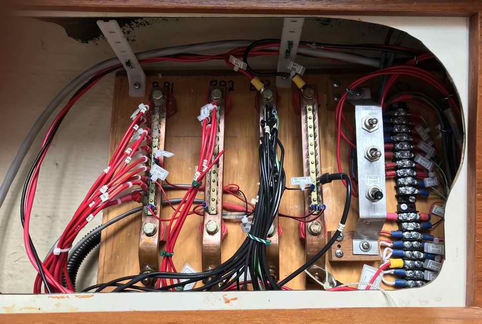
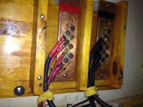 An excellent
buss bar can be fabricated from a 1/4" thick copper flat bar as shown here.
The length of the bars was chosen to match the number of terminations,
plus a spare position. The bars are mounted on thick UHMW
insulating standoffs so they can't short to earth. The wood dividers
separate (+) from (-) battery and the front is covered with clear acrylic for
impact protection. All wood is clear coated to prevent rot. This
panel is installed under the starboard settee with the battery installed
just to the left (aft) of the plywood. An excellent
buss bar can be fabricated from a 1/4" thick copper flat bar as shown here.
The length of the bars was chosen to match the number of terminations,
plus a spare position. The bars are mounted on thick UHMW
insulating standoffs so they can't short to earth. The wood dividers
separate (+) from (-) battery and the front is covered with clear acrylic for
impact protection. All wood is clear coated to prevent rot. This
panel is installed under the starboard settee with the battery installed
just to the left (aft) of the plywood.
The battery was
removed for this photo. It is a bit difficult to access this space
due to the companionway steps, but much improved if propped up on its
support stick.
Things could be worse!
These primary power distribution busses are electrically close to the battery, 1.5' of
cable (.5m), and the DC power panel, 3' of cable (1m) using #4 neoprene
welding cable. Welding cable has very fine strands that is
perfect to withstand the vibration on a boat. While Panache's power cables
are not
tinned, all connectors are crimped, soldered, sealed gas tight with sealed heat shrink. The exposed part of each connector is coated in dielectric grease. They have
never experienced corrosion.
NOTE - All power fed to the distribution
subpanel is filtered and against electrical noice by several ferrite chokes to block possible RFI generated by the solar charge controller, outboard generator or other unknown
source.
NOTE - By American Boat and Yacht Council (ABYC) Standards the negative power lead should be yellow, not black. In the telecommunications world where I live, negative is always black.
---------------------- TOP
------------------------
EARTH GROUND (WATER)
- To bleed off electrical "noise" on the boat's ground wiring it may be
desirable to connect the battery return buss (-) to an earth ground (water)
consisting of an underwater ground plate.
There are many ways to do this but I've always thought that a 1/8" or
thicker, half round copper pipe (2" diameter) fastened to the aft square
end of the keel would do the job. This would also require a 3/8" or
larger copper bolt at the top, protruding through the sealed hull, for the electrical connection.
Seal the bolt hole with butyl rubber and rubber grommets backed up with
flat washers/nuts inside and out.
See Siedarc
connectors or
Mark VII Wonderbar for this technique. This location would not
interfere with trailer launching. Leave the inside of the copper
pipe hollow for extra conducting surface and so water can drain out.
Bond the system earth wire to this bolt. Heck even the outboard leg touching the water might provide a good enough temporary ground for the communications. Just an idea I'm playing with.
However, installing an external earth ground may also invite electrolysis
from an adjacent boat in the marina or from dock power. So if you
have an electrically isolated power system that is "noise" free I suggest leaving well enough alone. NOTE - When it comes to wiring for shore AC power, DO NOT wire your boat like a floating house. The electrical standards established by the American Boat and Yacht Council (ABYC) clearly indicate that you should handle the entire boat as a grounded-type portable tool that has 3 conductors. Never ground both the hot wire and the shore-grounded neutral on the boat. The three most common errors that a boat owner makes are:
Connecting the grounded neutral wire (white) to the grounding wire (green). Omitting (or cutting) the green ground wire connection to the engine. Using equipment that requires both alternating and direct current not designed for a marine environment.
Read the ABYC standards before you wire. Making any of these mistakes can be very serious, if not disastrous, for a swimmer.
---------------------- TOP
------------------------
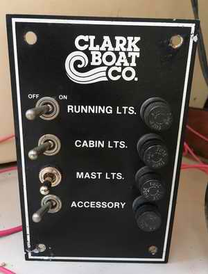
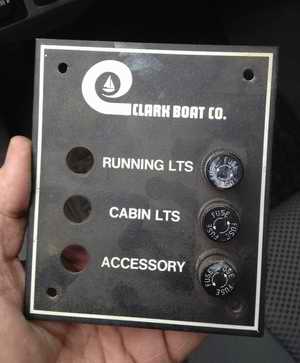 1 - POWER DISTRIBUTION PANEL FROM THE FACTORY
(Panache version 1, 1977)
-
The
factory
original
power distribution panel is pretty simple, consisting of only three
switches.
A later design included a fourth switch for a
steaming light (MAST LTS) as shown below.
Anything added to a panel was done by the owner as demonstrated by
Randy who replaced the original single pole MAST LTS switch with a dual pole
to operate either the anchor or steaming light. Clever way to improve
it without changing the panel. A schematic was never included in the
SJ23 manual as the
circuitry consisted of a single battery feed
connected to a
length of #10 solid wire soldered across the power inputs of the fuses.
The battery return for each load was wired directly to the negative terminal
of the battery instead of through the panel. Not the best method for
isolating a trouble but it works. All in all, pretty
simple and I think 1 - POWER DISTRIBUTION PANEL FROM THE FACTORY
(Panache version 1, 1977)
-
The
factory
original
power distribution panel is pretty simple, consisting of only three
switches.
A later design included a fourth switch for a
steaming light (MAST LTS) as shown below.
Anything added to a panel was done by the owner as demonstrated by
Randy who replaced the original single pole MAST LTS switch with a dual pole
to operate either the anchor or steaming light. Clever way to improve
it without changing the panel. A schematic was never included in the
SJ23 manual as the
circuitry consisted of a single battery feed
connected to a
length of #10 solid wire soldered across the power inputs of the fuses.
The battery return for each load was wired directly to the negative terminal
of the battery instead of through the panel. Not the best method for
isolating a trouble but it works. All in all, pretty
simple and I think
 for this reason, not worth mentioning in the manual.
Back in the 1970s presumably everybody knew
something about electricity! The panel was located on the
port side, above the
galley
stove. Now
there's a recipe for disaster if
I ever
saw one, sticking your hand over a steaming pot to flip a switch. I'll grant you it can be done quickly but any dose of steam to the dry
electrical contacts will hasten their demise due to corrosion. for this reason, not worth mentioning in the manual.
Back in the 1970s presumably everybody knew
something about electricity! The panel was located on the
port side, above the
galley
stove. Now
there's a recipe for disaster if
I ever
saw one, sticking your hand over a steaming pot to flip a switch. I'll grant you it can be done quickly but any dose of steam to the dry
electrical contacts will hasten their demise due to corrosion.
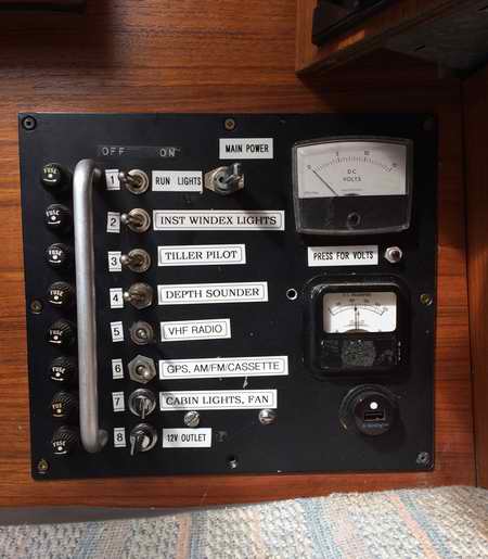
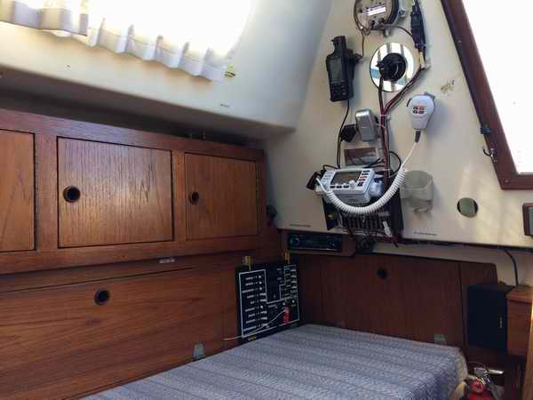
2 - POWER DISTRIBUTION PANEL E/W SWITCHES & FUSES
(Panache version 2, 2002)
-
The
factory panel
didn't have the capacity to handle the eight circuits I wanted, so I
fabricated an electrical panel with switches, fuses and 2 meters. It was
installed at the aft end of the starboard settee directly above the battery
for lowest power loss via short wiring.
 This location is out of
the weather and away from the cook, which is rather important if you think
that getting fed is of any significance to your existence on this planet! The
mechanical assembly should be within the capabilities of most handymen with
opposing thumbs! The wiring is fairly straight forward. If you
can't do it, find yourself an electronics "nut". Many of them are only
too willing to help in exchange for a day of sailing. This location is out of
the weather and away from the cook, which is rather important if you think
that getting fed is of any significance to your existence on this planet! The
mechanical assembly should be within the capabilities of most handymen with
opposing thumbs! The wiring is fairly straight forward. If you
can't do it, find yourself an electronics "nut". Many of them are only
too willing to help in exchange for a day of sailing.
The
aluminum bar protected the switches against accidental operation from a
'sleeping giant' who likes to stretch his legs and sometimes throws gear on
the bunk. This was a lift handle I scrounged from an old
telecommunications test set.
The voltmeter at the top of the panel measures battery voltage via the red
momentary switch just below it. The 500MA ammeter below it measures
solar panel charge current to confirm operation. This meter is
probably WWII vintage. The
12VDC accessory outlet at the bottom right corner is
fused and
usually houses a USB charger. I occasionally plugged a 300W inverter
in it for AC power. Click here to see the
schematic
for this panel.
TOP
 3 - POWER DISTRIBUTION PANEL E/W CIRCUIT BREAKERS (Panache
version 3, 2017) - I
pondered long and hard to fabricate a new distribution panel to replace the
working fuse panel. I had the parts and the tools. I just
needed a justification which materialized with a recurring intermittent connection
that limited how much power I could draw from the panel. So, the new design included 15 DC circuit breakers, 2 digital panel meters, 1 DC outlet, 1 AC outlet and a tripped breaker alarm. Then I discovered the retail cost of this panel would cost on the up side of
$1200 Ca (2017). Yikes! Most of the parts came to me as surplus communications equipment from various sites I worked at. Deep down I always knew scrounging was a worthwhile
endeavour. 3 - POWER DISTRIBUTION PANEL E/W CIRCUIT BREAKERS (Panache
version 3, 2017) - I
pondered long and hard to fabricate a new distribution panel to replace the
working fuse panel. I had the parts and the tools. I just
needed a justification which materialized with a recurring intermittent connection
that limited how much power I could draw from the panel. So, the new design included 15 DC circuit breakers, 2 digital panel meters, 1 DC outlet, 1 AC outlet and a tripped breaker alarm. Then I discovered the retail cost of this panel would cost on the up side of
$1200 Ca (2017). Yikes! Most of the parts came to me as surplus communications equipment from various sites I worked at. Deep down I always knew scrounging was a worthwhile
endeavour.
Design criteria and features of this panel:
- A
circuit breaker requires slightly less space than a
switch/fuse combo making it possible to install more circuits in the same space;
in Panache's case from 8 circuits to 15.
- The contrast of a white breaker lever against a black panel makes it
easy to see the on/off status at a glance as evident in the photo.
- The current rating of a
breaker is normally sized to protect the wire. Panache uses 15A
breakers and with a spare in the cabinet.
- The Breaker Panel is latched by a couple of
brass barrel bolts and flips down on brass hinges for
ready access to the back. There is just enough
space behind the panel to prevent wire movement without squishing it. This
"squish" space
is very important so the connections are not strained and with
enough ventilation to keep it dry.
- The adjacent settee back rest can flip down to access the
Secondary Buss Panel wiring. There is sufficient
slack in the wiring to slide the back panel sideways a bit for servicing.
-
All wiring is labelled showing from/to termination ends of a wire.
-
All extra or defective wiring was removed to eliminate clutter and confusion.
-
A toggle switch was later added to the panel to direct power to the steaming or
deck light.
-
An external LED
spotlight illuminates the front of the panel nicely for night operation. It
is connected to permanent power to service the wiring with the main
power switched off. I will still need a head light to move around.
There is usually some obstacle that rears its ugly head when developing
new hardware and I didn't want to go down the proverbial garden path of
having forgotten a circuit, an illogical layout or difficult wiring as with the
previous fuse panel. That's the
main reason why I progressed slowly with this upgrade. The thing about
low loss, large gauge wiring is that it can't bend like small gauge can, so
planning the component layout was important.
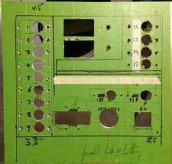 Q
- Ever wonder why the new panel is green? Q
- Ever wonder why the new panel is green?
A - Its a lot easier to write on an aluminum
panel covered with Frog Tape. Then if you get it wrong, apply new
tape for a new mistake! It's also great to write a note on.
Electrical Protection - The primary function of a circuit
breaker is to protect the downstream wiring against an electrical short from loose wiring, worn insulation or any other reason you can
dream of! For this reason a breaker is installed at the power
source. Take this seriously if you don't want to experience a
fire on the water or on the road. Fire is nasty stuff. The
secondary function of a circuit breaker is to leave the other circuits operational
while a defective one is isolated for service. To be totally
effective each circuit must have its own breaker.
NOTE 1 - The World Single Pole Magnetic AC/DC Circuit
Breaker meets all American Boat and Yacht Council (ABYC) Standards, is UL
1077 Recognized, CSA Certified for Canada, TUV Certified and CE marked for
Europe.
Battery Return Wires & Single Point "Grounding" - All loads are
wired with their own battery return wire (often
mistakenly called a ground wire) terminated on a common
negative power buss bar Never use a metal boat part, mast
or toe rail, for a return conductor.
LOAD RETURN WIRES - With this breaker panel each device has its own
battery return wire (usually #10 stranded black) connected
to the common negative return buss bar (BB3) on the
Secondary Buss Panel. The battery return wire
for BB3 is a black
#4 weld cable connected to the primary negative buss bar (BB0) which is
then connected to the battery negative post. Connecting them in this
order eliminates circulating current in the wiring. If you don't
achieve single point grounding, the laws of chemistry and physics will
apply and you won't be happy with the electrical "noise" affecting your
electronics!
EARTH GROUND - At this point in time Panache has a single conductor
to bleed off electrical "noise" or static charge from the primary negative
buss to the water (earth / ground) using the immersed outboard
leg. So far a sacrificial anode to prevent electrolysis of
the aluminum leg is not required but I'm always looking. I may install a dedicated lightning ground in the future.
More below.
Large Gauge Battery Wires - In Panache's configuration the 12V power
is sourced from the battery positive post to the primary buss bars (BB0) and is
filtered with 2 ferrite beads to block RF noise from the outboard
generator. Then the power is
fed to the secondary buss bars (BB1, BB2), using #4 weld red cable. Finally the power from the secondary buss bars is connected to
each breaker via a
#10 stranded red wire. Each breaker is connected to its load
with
#10 stranded red or smaller gauge wire. The very low power devices operate on smaller 16 gauge wire.
Connector Corrosion - A dry metal connection exposed to a humid
environment will corrode and deteriorate in a year, or less. This is
basic chemistry and physics, so learn to live with it. The
prevention is to keep oxygen away by coating the connection with a drop of
ATF or synthetic oil. Either oil has the advantage of creeping into an
unseen crevice for complete protection and it doesn't wash off. It
is easy to apply and if done sparingly, keeps things clean. Apply a
drop once a year for continued protection. Alternatively spraying lithium
grease or smearing a light coat of synthetic grease on each
connection also works but is definitely messy. Switches and
circuit breakers must be operated occasionally to function properly.
The wiping action keeps the contacts clean.
More below.
|
|
SECTION 2 - PANEL COMPONENTS COMPONENTS
& SUB CIRCUITS - Electrically the circuit breaker panel is the same as a switch & fuse panel. Physically it is quite different to incorporate the new hardware and features. In this system the positive wire is protected (circuit breaker) as close as possible to the source of power to minimize the wiring with power still on which also reduces corrosion on the power distribution wires. The description of each component below follows the power flowing from the battery to each load, which should make this easier to understand.
-
BATTERY - Optima 55AH 12V AGM battery
charged by 2 solar panels (sometimes a third panel) and a 6 amp generator in the outboard. See Tech Tip E01 for charging the battery.
-
MAIN DISCONNECT CIRCUIT BREAKER (BKR 0) -
125A circuit breaker (normally on) is installed under the starboard settee. It is wired between the house/starter battery and the primary buss bars to automatically disconnect all system power in the event of a major electrical short.
- Opening this breaker will eliminate all drain on the battery, except to the charge controller which can be disconnected with Bkr 12.
- The charge controller bypasses BKR 0 as it is wired directly to the battery to maximize charging.
-
PRIMARY POWER DISTRIBUTION BUSS BAR (BB 0) - Nothing complicated here. Just a couple of copper buss bars to securely terminate the battery leads; the starter/generator cables of the outboard and the cables to the secondary buss bars. It the safest way to securely distribute power to the breaker panel.
The power flowing to the secondary the buss bars is
filtered by several ferrite beads to block RF voltage spikes from the outboard generator or a PWM solar charge controller that was previously installed.
NOTE - Panache's PWM charge controller was replaced by a MPPT charge controller in 2020. The ferrite beads were left in place to filter potential noise from the outboard generator.
-
SECONDARY POWER DISTRIBUTION BUSS BARS (BB 1-4, SW 1-3 & TERMINAL STRIPS TS 1-2, all on the Back Panel) - The secondary buss bars are located on the back panel (behind starboard settee back rest) to distribute power as follows:
Terminal |
BB 1 (+) |
BB 2 (+) |
BB 3 (-) |
BB 4 (-) |
SW 1-3 |
TS 1 |
TS 2 |
| Description |
Switched power to circuit breakers. (transient protected) |
Constant power to circuit breakers. (transient protected) |
Power return for all devices except the inverter and deck wash pump. |
Power return for devices with high start current; inverter, deck wash pump. (The current bypasses meter M2 so it does not burn out the internal shunt of the meter) and the transient suppressors TVS 1&2. |
Switches to manually operate bilge pumps. |
Media player memory & constant power to 3 bilge pumps. |
Switched power to the cabin devices. |
I added a back panel to mount the secondary buss bars to organize the wiring for a trouble free installation. I originally wanted to install this panel behind the breaker panel but the space behind is not deep enough. Instead, I placed the back panel behind the aft back rest, to the left of the breaker panel. The plywood back panel rests on a vinyl grid to keep it high and dry. The wires from the breaker panel are intentionally spread loose along the bottom of the cavity, resting on the same vinyl grid. This makes it easy to trace the suspected wire and to prevent cross talk of wires carrying data. The connectors are not strained nor is the wiring squished together, which goes a long way towards maintaining the integrity of the connections. Labeling makes it easier to trace wires and to find components.
NOTE - (The power on each positive buss
bar BB1 & BB2 is protected by a P6KE transient voltage suppression (TVS) diode that drains a transient to the battery return buss BB4. These 2 diodes clamp a transient voltage in nanoseconds, effectively shorting a transient to a maximum of 36VDC before it can rise to a damaging level.
Also see Tech Tip E01)
The back panel (L to R) showing BB1 switched power buss bar.
BB2 constant power buss bar. BB3 battery return buss bar.
BB4 battery return buss bar (to bypass meter M2 shunt). S1, S2, S3 bilge pump switches. TS1 media player (top) & bilge pumps (bottom). TS2 cabin lights (hidden to right).
NOTE - The labelled wires to each device lay loose along the bottom to easily trace a problematic one.
|
TERMINAL STRIP TS1 (top), BACK PANEL. |
|
PIN # |
EXTENSION CABLE |
KENWOOD
HARNESS |
KENWOOD MEDIA PLAYER |
| 01 |
1 - Wh |
Wh |
Speaker FL + (bulkhead). |
| 02 |
1 - Gn |
Wh/Bk |
Speaker FL - (bulkhead). |
| 03 |
1 - Rd |
Gr |
Speaker FR + (bulkhead). |
| 04 |
1 - Bk |
Gr/Bk |
Speaker FR - (bulkhead). |
| 05 |
2 - Wh |
Gn |
Speaker RL + (companionway). |
| 06 |
2 - Gn |
Gn/Bk |
Speaker RL - (companionway). |
| 07 |
2 - Rd |
Vi |
Speaker RR + (companionway). |
| 08 |
2 - Bk |
Vi/Bk |
Speaker RR - (companionway). |
| 09 |
3 - Wh |
Bl/Wh |
Antenna power -
(not used). |
| 10 |
3 - Gn |
Bl/Yl |
Auto steering wheel control -
(not used). |
| 11 |
3 - Rd |
Rd |
Switched power. (BKR 8, Media Player) |
| 12 |
3 - Bk |
Bn |
Mute control. (not used). |
|
BKR 14 |
Direct connect |
Yl |
Constant power. (BKR 14, Memory) |
|
TERMINAL STRIP TS1 (bottom), BACK PANEL. |
|
PIN # |
POWER
(BKR 15) |
PUMP HARNESS |
BILGE PUMP WIRING |
| 13 |
12V Mult |
Rd1 <-- Yl |
Bilge pump 1 - settee starboard, float switch 1. |
| 14 |
12V Mult - S1 |
Rd2 <-- Bn |
Bilge pump 1 - settee starboard, toggle switch, S1. |
| 15 |
12V Mult |
Rd1 <-- Yl |
Bilge pump 2 - settee port, float switch 2. |
| 16 |
12V Mult - S2 |
Rd2 <-- Gn |
Bilge pump 2 - settee port, toggle switch, S2. |
| 17 |
12V Mult |
Rd1 <-- Yl |
Bilge pump 3 - cockpit port, float switch 3. |
| 18 |
12V Mult - S3 |
Rd2 <-- Gn |
Bilge pump 3 - cockpit port, toggle switch, S3. |
| 19 |
(vacant) |
|
|
| 20 |
(vacant) |
|
|
|
BB3 |
Direct connect |
Bk |
Battery return for each device. |
|
TERMINAL STRIP TS2, BACK
PANEL. |
|
PIN # |
POWER
(BKR 09) |
CABLE |
CABIN LIGHTS, FAN & GALLEY PUMP |
| 01 |
Mult 12V |
- |
(vacant) |
| 02 |
Mult 12V |
- |
(vacant) |
| 03 |
Mult 12V |
Rd |
Post lights, fwd & aft. |
| 04 |
Mult 12V |
Rd |
Galley pump. |
| 05 |
Mult 12V |
Rd |
Port wall lights, ceiling night light, fan. |
| 06 |
Mult 12V |
Rd |
Starboard wall light, fwd. |
| 07 |
Mult 12V |
Rd |
Starboard wall light, aft. |
| 08 |
Mult 12V |
Rd |
Galley light. |
| 09 |
Mult 12V |
- |
(vacant) |
| 10 |
Mult 12V |
- |
(vacant) |
|
BB3 |
Direct connect |
Bk |
Battery return for each device. |
---------------------- TOP
------------------------
-
BREAKER PANEL ( E/W Circuit Breakers, Meters and 12V & 115V Outlets) -
The table below approximates a front view of the panel layout. The bracketed numbers in red denote the measured current drawn by each circuit.
|
BREAKERS,
(Switched Pwr from BB1)
1 NAVIGATION LIGHTS (.23A)
2 STEAM / DECK LIGHTS (S4),
(.08A, .11A)
3 INSTRUMENT & WINDEX LIGHTS (.065A)
4 AUTO PILOT (Stdby .040A, Auto
.5 to 1.5A)
5
DEPTH SOUNDER (.028A) / GPS (.06A)
6 DECK WASH PUMP (~10A)
7 VHF RADIO (stdby .38A, Lo
1A, Hi
5A)
8 MEDIA PLAYER (4A)
9 CABIN (5 Lites
.34A, Fan
.32A, Galley pump .6A)
|
-
CHARGE METER
(M1 & S1)
(.02A)
-
DISCHARGE METER
(M2 & S2)
(.02A)
|
BREAKERS, (Constant Pwr from BB2)
12. SOLAR PANELS (0 to 3.2A)
13. ANCHOR LIGHT (.03A)
14. MEDIA PLAYER MEM (.2A, .18A, .005A)
15. BILGE PUMPS
1 stbd settee (.42A)
2 port settee (.30A)
3 port locker (.70A)
|
|
BREAKER ALARM &
ACO -
(S3, Sonalert, LED)
(0 - .12A)
|
|
MAIN POWER SWITCH - (S0) |
10. 12V OUTLET
(10A max)
|
11. 115VAC OUTLET
(25A max)
|
|
Typical electrical load, night sail = (.6 to .7A)
|
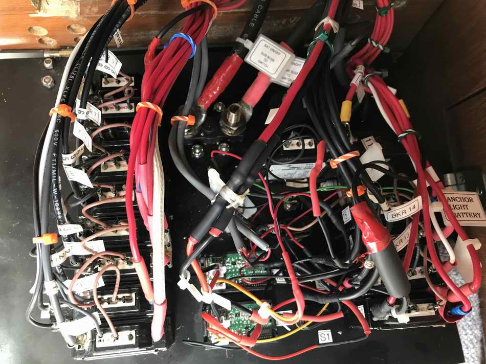
The breaker panel is flipped down to show components on the back. It may look like a rats nest but each wire was selectively picked, verified and connected during installation to confirm all are correct. Not all battery wires are red. It just wasn't practical to replace a perfectly good wire in an installed harness so I just crimped and soldered the correct lug on the end then sealed the end with red heat shrink.
The bundles of wires at the hinge are left loose to prevent flex fatigue. The two shielded sense wires (grey) from the panel meters (2 green circuit boards) are secured to the white cable standoff post to eliminate fatigue to the delicate panel meter connectors. The slack in the wire is to permit install or removal of a meter.
(Its a difficult thing to photograph so please excuse the poor lighting).
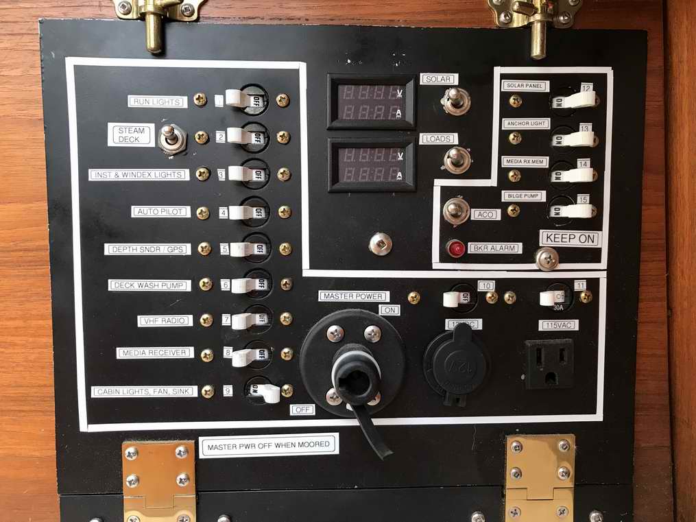
Each
bank of 15A breaker switches below is outlined with pin striping on the front of the panel for quick understanding of switched battery to the left (NORMALLY OFF) and permanent on battery to the right (KEEP ON), with panel meters and toggle switches between.
This is so another guy can find the switch! I never have this problem myself you understand! The front panel flips down on two beefy brass hinges to access the wiring behind (shown above) and is secured upright by two brass barrel bolts for operation (below).
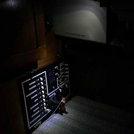
The breaker panel is flipped up and latched with
the charge meter (M1) measuring 17.4V and the discharge meter (M2) measuring battery voltage of
13V
. This high input voltage measured by the charge meter
(M1) is indicative of an MPPT
solar
charge controller output. Each meter can handle 10A.
NOTE - Not all the segments of a panel meter show when photographed with a digital camera since the power to each segment is multiplexed. To the naked eye they appear fully
illuminated
and readable. Its a clever trick to take advantage of the slow response of the human eye while
saving power.
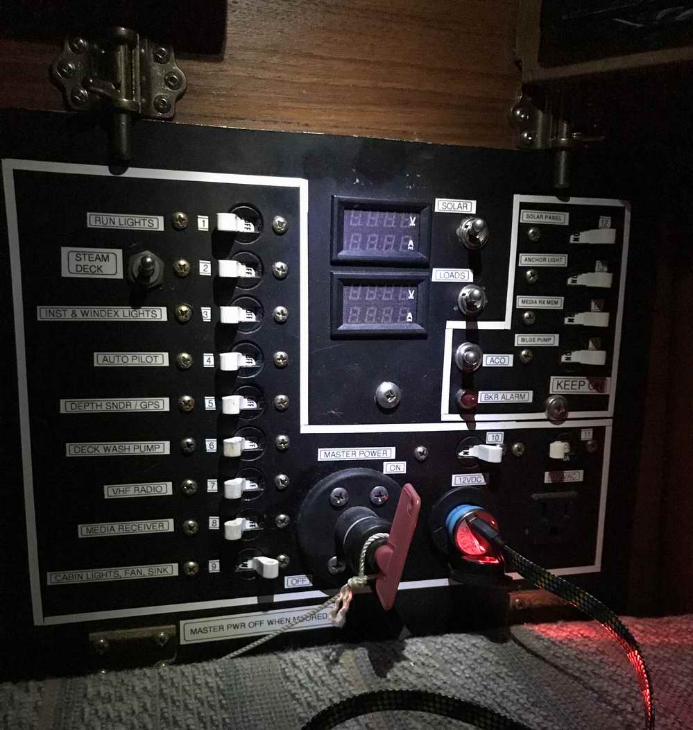
It only takes one LED to illuminate the panel at night. My cell phone is being charged from the 12V outlet.
---------------------- TOP
------------------------
-
MAIN POWER SWITCH (S0) - A Moeller Marine
battery disconnect switch (110A @ 12V) controls power (manual operation) to breakers B1-B11. This switch is equipped with a removable key to prevent unauthorized use. The power is switched off when Panache is unattended. If there were two house batteries in this system I would install an OFF/1/BOTH/2 switch.
Note - The power fed to this panel is filtered by ferrite beads at the primary power buss bar.
-
METER SWITCHES (S1 & S2) - S1 solar charge current. S2 discharge current. The switches are normally off to minimize power drain.
-
ALARM CUT OFF SWITCH (S3) - The switch is normally on to hear an alarm and off to quiet alarm.
CIRCUIT BREAKERS
1-11 (Fed by Switched Power from Distribution Buss BB1)
- This bank of similar function breakers is clustered on the left side of the panel. They are manually operated to switch power to each load as required. Some may be left on with the power controlled by a switch on the device. The life of a breaker is reduced by using it as a switch.
NOTE -
Next time a thunderstorm comes your way consider shutting off ALL the circuit breakers to protect the electrical system and devices against an Electromagnetic Pulse (EMP). Make it a habit to leave the breakers OFF when you leave the boat.
Bkr 1 (Navigation lights, 15A) - This breaker
is sized for 3 incandescent bulbs just in case I have to replace an LED bulb back to an incandescent bulb. Given the life of an LED I doubt this will ever happen.
(If you wish to install an LED tri-light on the mast head as an alternate to the hull mounted running lights then install a single throw double pole switch after BKR 1 to direct power to either set of lights, NOT both. It is confusing and therefore illegal to illuminate two sets of navigation lights on a boat. The double pole switch will eliminate confusion and ensure legal compliance. It is common to use a tri-light for visibility in deep ocean troughs and the hull lights in a harbour.)
Bkr 2 (Steam or deck light, 15A) - This breaker feeds power to switch S4 (single throw double pole), a 2 position switch that directs power to the steaming light (up) or deck light (down). See panel photo above. There was just enough space to install this adjacent to BKR 2 to make it easy to understand.
Bkr 3 (Instrument Lights, 15A) - Ritchie Compass, Signet Knotmeter, & Windex.
Bkr 4 (Auto Pilot, 15A) -
Raymarine Tiller Pilot ST2000.
Bkr 5 (Depth Sounder & GPS, 15A) -
Haweye D10DX and
Magellan GPS320 Receiver.
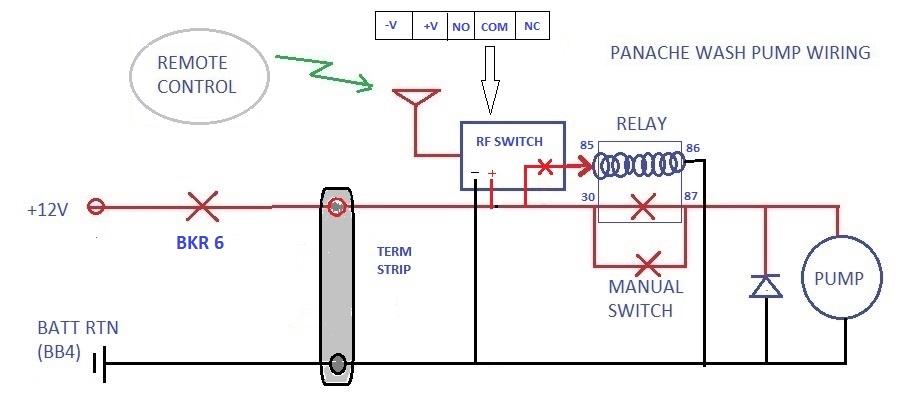
Bkr 6 (Deck Wash Pump, 15A) - 12V Utility Pump. See Tech Tip E19.
Bkr 7 (VHF, 15A) -
Standard Horizon Explorer GPS GX1700W.
Its useful to install a quick blow fuse on the battery return wire to protect the VHF against an air induced power surge.
Bkr 8 (Media Player, 15A) - Kenwood KMM-BT315U.
Bkr 9 (Cabin Power, 15A) - This breaker feeds power to
Term Strip 2, from which all cabin power is fed (lights, fan, galley pump).
Bkr 10 (12V Outlet, 15A) - This breaker feeds power to the 12V outlet located at the bottom right corner of the panel.
This style outlet is best suited to a cigarette lighter. The inexpensive versions are notorious for a having a poor, intermittent connection that also has considerable voltage drop. As much as I dislike it, there are many devices still wired to connect to it so I'm stuck with having to install one. I installed the best quality I could find.
- There is usually a 12V USB adapter plugged in this outlet to charge a cell phone.
A caution about a low grade USB adapter that may radiate RF and
interfere with the VHF radio.
The quickest way to determine if RF interference is your problem it to shut off the power to the USB adapter.
- I may connect a wireless charger for my cell phone to this breaker.
 Bkr 11 (110VAC Outlet, 15A) -
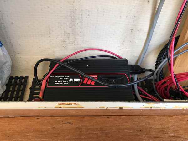
This 30A breaker feeds power to a 400W pure sine wave inverter (installed 2024) that supplies
115VAC to the AC outlet located at the bottom right corner of the panel.
A pure sine wave inverter draws ~35% less power from the battery than a modified sine wave inverter. Sensitive electronics can operate safely from it without burning out.
See NOTE 2 below.
To further reduce power consumption, the cooling fan runs only when required. Bkr 11 (110VAC Outlet, 15A) -
This 30A breaker feeds power to a 400W pure sine wave inverter (installed 2024) that supplies
115VAC to the AC outlet located at the bottom right corner of the panel.
A pure sine wave inverter draws ~35% less power from the battery than a modified sine wave inverter. Sensitive electronics can operate safely from it without burning out.
See NOTE 2 below.
To further reduce power consumption, the cooling fan runs only when required.
- Unfortunately I cannot measure the DC current this inverter draws. But I operated a Dremel Tool for about 30 minutes and the solar panels restored the battery charge after only 5 minutes in full sun. This indicates the inverter drew little power from the battery and/or the solar panels had no problem keeping up to the lower power draw. This is significantly better operation than my previous stepped sine wave inverter.
- Since the inverter draws a significant surge current when starting, it will overload the internal shunt in
discharge meter, M2. Therefore the battery return wire is connected to (BB4-11), bypassing the shunt. This wire gauge is sufficient to drive the inverter to full output, continuously.
- NEVER connect the AC neutral of an inverter to boat ground as this is hazardous. Leave it isolated. Panache's inverter draws power only from the battery. As such it cannot connect to shore power where it may create an unintended hazardous ground path or start electrolysis via the outboard leg (if left in the water). The electrical path combinations with shore power and adjacent boats is very complex and difficult to measure.
NOTE 2 - The power from a modified sine wave inverter
(stepped sine wave) may likely burn out a device that has an inductive load like a transformer, motor or switching power supply. But it is safe to connect a resistive load like a soldering iron. Since a true sine wave inverter draws ~35% less power than a modified one it is a good example of you get what you pay for!
-
 BREAKERS
12-15 Alarmed (Fed by Constant Power from Distribution Buss BB2) - The power fed to the alarm contacts of the 4 breakers at the top right of the panel comes from buss bar BB2 (constant power), bypassing the main power switch (S0) on the breaker panel. These breakers are
normally left ON. A breaker goes to alarm state when off. BREAKERS
12-15 Alarmed (Fed by Constant Power from Distribution Buss BB2) - The power fed to the alarm contacts of the 4 breakers at the top right of the panel comes from buss bar BB2 (constant power), bypassing the main power switch (S0) on the breaker panel. These breakers are
normally left ON. A breaker goes to alarm state when off.
Alarm Circuit - The common contacts of the alarm contacts inside breakers 12-15 are daisy chained together (light black wire drawn through each breaker in diagram) to power a Sonalert (SA) and illuminate the LED
if one of the breakers trips or is switched off (alarm condition). However,
the combined alarm signal is wired through an Alarm Cut Off (ACO) switch to silence the thing because there is nothing more irritating and interfering than a loud alarm when trying to isolate a trouble. The LED draws your eye to the alarm condition, especially at night.
Bkr 12 (Solar Panels, 15A) - Controls power from the 2 solar panels on the sliding hatch, and a temporary 3rd panel wired to the cockpit.
(Technically I don't need this breaker because the ampacity of the wiring exceeds the power output of the panels. In Panache's case BKR 12 functions as an on/off switch that has current protection).
Bkr 13 (Anchor Light, 15A) - Supplies constant power to the anchor light that switches automatically with darkness.
Bkr 14 (Media Player Memory, 15A)
- Supplies constant power to maintain media player memory configuration.
Bkr 15 (Bilge Pumps, 15A) - Supplies constant power to operate the 3 bilge pumps automatically via their float switches. There are also 3 switches on the back panel to operate each pump manually. See Tech Tip E16.
-
SOLAR CHARGING CIRCUIT - The combined 3A output of the two sliding hatch mounted solar panels are switched through breaker B12 so charging power to the system can be shut off to service the wiring and electronics safely.
A temporary third solar panel can be added to offset high electrical loads while working at the dock.
(To protect a solar charge controller the
 INPUT POWER MUST be switched off first, then the output power. Switching the output power off with the input power on may damage the charge controller). The output is protected with an internal 20A automotive style fuse. The instantaneous voltage and current of the solar power can be verified on charge meter M1 or the LED display on the charge controller. While its OK if the charge current exceeds the panel meter rating (10A) for a short time, it is not recommended. The #10 gauge wires to and from the solar charge controller ensure quick battery charging with clean power for the electronics. INPUT POWER MUST be switched off first, then the output power. Switching the output power off with the input power on may damage the charge controller). The output is protected with an internal 20A automotive style fuse. The instantaneous voltage and current of the solar power can be verified on charge meter M1 or the LED display on the charge controller. While its OK if the charge current exceeds the panel meter rating (10A) for a short time, it is not recommended. The #10 gauge wires to and from the solar charge controller ensure quick battery charging with clean power for the electronics.
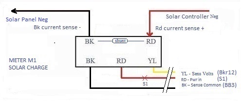
NOTE - By convention the exposed contacts of a shunt MUST be installed in the battery return path, so the exposed wire is at a safe 0V. This wiring configuration also ensures the meter measures a "steady" DC current if there is a PWM charge controller. See
Tech Tip E01.
-
OUTBOARD STARTER / GENERATOR
- The outboard starter / generator (6A) is connected directly to the primary buss bars (BB 0) so the starter can draw maximum power from the battery, bypassing the breaker panel. With the engine running, the generator automatically charges the battery through Bkr 0. So far I have not seen it necessary to install a breaker or fuse in this circuit for the following reasons:
- The momentary starter switch on the outboard is normally open, creating protection.
- The generator uses the same wires as the starter and has a diode to prevent reverse current flow.
- The main Bkr 0 will provide some automatic protection.
- If I'm on board I can always unplug the outboard at the transom or switch off the main breaker, B0.
- If it should prove necessary, I will install an inline automotive fuse.
-
DIGITAL PANEL METERS (M1 & M2) - Due to limited space on the front panel I installed two digital panel meters (M1, 10A solar charge current) & (M2, 10A load discharge current). Both meters have an internal shunt to measure up to 10A current, freeing up space on the back panel where an external shunt would be installed.
- Each meter operates on <20MA at 4.5-30VDC that is sourced from the switched power buss, BB1.
Input power is controlled by toggle switches S1 & S2, when I want to measure the values. I considered a momentary switch but constant power to these meters frees up my hands if I have to service the system.
M1 (Solar Charge) - This volt sense is wired to the output of Bkr12 to confirm the presence of solar power.
M2 (Load Discharge) - This volt sense is wired to the switched power buss BB1, to measure house battery voltage.
NOTE - The battery voltage on M2 may show up to 21V when the outboard generator is charging. This is not a fault. These meters show peak voltage, not RMS and the outboard generator sends pulsing DC power to the battery.
 |
|
 |
- Meter M1 -
A 10A panel meter wired to measure charge voltage & current from all (3) solar panels.
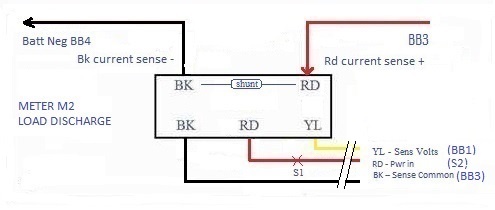
- Meter M2 - A 10A panel meter wired to measure discharge voltage & current to all loads except the inverter.
- Operating Power: 4-28VDC @ <20MA.
- Measuring Range: 10A via internal shunt, 200VDC with .08% resolution and 3 decimal place display. Can be field calibrated.
NOTE - A shunt can measure current in only one direction. If it is wired backwards some meters can't show a reading and others show an abnormal reading of ~2.2A. Simply reverse the wires to show the correct reading. No damage done. A purpose made battery monitor is superior to using a simple volt & ammeter because it can calculate ampere hours consumed (integrating current in & out of battery) and show the state of charge (SoC) of the battery. EG: Victron BMV-700. |
|
PANEL METER M1 SOLAR CHARGE (Power & Sense Leads)
|
|
M1 LEAD COLOUR & DESCRIPTION |
(EXTENSION CABLE, M1) |
CONNECTION |
FUNCTION |
|
Rd - Power in |
(Rd) |
To S1 & BB1 (switched power buss). |
Meter power, on/off via S1. |
|
Bk - Power gnd & sense common |
(Gn) |
To BB3 (battery return buss). |
Meter power, common battery return for all devices except inverter. |
|
Yl - Sense volts |
(Bk) |
To Bkr12, solar charge controller positive. |
Measure solar charge voltage.
(0V when Bkr12 is open). |
|
Bk - Shunt current sense - |
Bk |
To solar panel, negative. |
Measure solar charge current out. |
|
Rd - Shunt current sense + |
Bk |
To solar charge controller, negative. |
Measure solar charge current in. |
|
|
|
PANEL METER M2 LOAD DISCHARGE (Power & Sense Leads)
|
|
M2 LEAD COLOUR & DESCRIPTION |
(EXTENSION CABLE, M2) |
CONNECTION |
FUNCTION |
|
Rd - Power in |
(Rd) |
To S2 & BB1 (switched power buss). |
Meter power, on/off via S2. |
|
Bk - Power gnd & sense common |
(Bk) |
To BB4 (battery return buss). |
Meter power, common battery return for all devices except inverter. |
|
Yl - Sense volts |
(Bk) |
To switched power buss, (BB1). |
Measure battery voltage. |
|
Bk - Shunt current sense - |
Bk |
To BB4. |
Measure negative
load current out. |
|
Rd - Shunt current sense + |
Rd |
To BB3. |
Measure
positive load current in. |
|
NOTE - If you replace a defective meter with one from another manufacturer confirm that the pin assignment at the connectors are identical before you plug the cord into the new meter. Usually the function stays with the wire colour which might be wired to a different pin on the connector, forcing you to move & splice wires to maintain function.
|
|
SENSE LEAD WIRING - The panel meter sense leads are delicate and too short to reach the back panel. So I soldered them to an extension cable that has a slightly larger gauge wire. (Don't install a terminal strip next to the meter using mechanical connections. A panel meter measures extremely low voltages (MV range) and any corrosion in a connection will create a false reading). The 2 extension cables are also secured to a stand off post to eliminate vibration fatigue at the meter connectors.
See table above to translate the panel meter wire colours to my extension cable colours. For simplicity the meter schematics above don't show the extension cables.
NOTE - The extension cable leads are labelled by function & location for future service. You will forget!
|
---------------------- TOP
------------------------
|