| SJ23 Tech Tip E09, (Updated 2014-03-13) Bob Schimmel & Dave Finley | |
|
Wiring Inside the Mast. |
|
|
There is nothing more frustrating than intermittent electrical wiring, especially if it's inside the mast and it will fail when you need it most. Picture yourself motoring during the evening in a busy seaway and you are converging with a tug boat pulling a heavy barge. The tug automatically has the right of way because it can't manoeuvre. To avoid the tug you alter course to give it lots of clearance. Just then your steaming light starts to flicker. Not a situation that anybody wants since you are presenting a confusing signal to the tug boat skipper. This is one of those situations that makes hair turn white, quicker than normal! You quickly switch on a flashlight and confirm your heading via VHF to anyone listening. All is OK between you and the tug BUT, showing just your navigation lights doesn't reflect the fact that you are motoring so you better pay extra vigilance as you proceed along the edge of the traffic lane. Careful with that flashlight though, a flickering light will give a confusing signal to the next oncoming vessel. What started out as a nice moonlight trip through the harbour has become a downright dangerous situation due to an intermittent wire. OK I know I'm exaggerating a bit but the next morning you decide to repair the mast wiring! Since this requires you to open the mast, you may as well inspect the halyards and sheaves as well. (See Tech Tip F03). The description that follows is a technique for supporting the electrical wiring inside the mast so it doesn't get damaged and works all the time. The system on Panache has operated without fail since 1998. INSTALLATION CONSIDERATIONS - Determine which type of electrical
connectors you will use at the ends of the wires. This may
determine where you can install them or may restrict the layout of the
installation. If you have internal halyards it is important to
separate the wiring from the halyards. This can be done by keeping the
halyards on the aft side of the spreader
MAST HEAD & FOOT -
The factory fastened the mast head and foot with
aluminum pop rivets or machine screws. Pop rivets are
easy to remove if you use an oversize bit to drill through the head
till it spins free, then drive the shaft through with an exact
fitting drift
punch. Remove the shaft from inside the
mast. If a machine screws is so corroded that it can't be
screwed out, dribble some
vinegar on
the thread and have a beer, or two, before you tackle them again! The alternative is to
use an "easy out" (poor man's impact wrench) on the head of the screw.
Quicker than beer but not nearly as much
fun. An "easy out" is equipped with interchangeable drive tips to match the screw and
has an internal reverse
thread that turns the
screw out when you hit the end of the tool with a sledge hammer. Don't be
afraid to drive it really hard. A single heavy blow will work where
a bunch of light taps don't.
If your mast head or foot fitting was attached with pop rivets or sheet metal screws, replace them with 1/4" stainless steel machine screws. Screws are stronger and easier to twist in the future. Read the note from Dave Clark at the bottom of Tech Tip F17. I'd be tempted to install four screws for ultimate strength. It's OK to install a slightly oversize screw (relative to the pop rivets) since you will have to drill out the hole to get clean metal to tap the new thread. Drill the hole through the thickest metal of the mast foot to hold the screw since it will be under considerable shear load when stepping the mast. Smear the thread and underside of the head with Vaseline to prevent galling or corrosion. While you have the head off, you may as well inspect the sheaves and dividing plate as per Tech Tip F03. Install an LED anchor light at the masthead for low power consumption and greater reliability. With the low power consumption you might be tempted to install lighter gauge wire to save weight aloft but it isn't worth the effort. You need the larger gauge to maintain voltage. It is nice to know that the Windex or anchor light won't drain the battery after an overnight sail. Wiring through mast head. TOP
When you push the hollow braid together it opens the core so you can push the electrical cables through. If you use a fid over the wire ends to work them through the hollow braid it makes the job quite easy. With the cables sticking out the top end of the hollow braid, splice a 1" diameter loop of braid at the end by tucking 2' or more of braid back inside itself, similar to splicing yacht braid. I followed this up with a whipping of waxed twine to secure the loop and the wires. Now you will have a nice strong loop with 2' of cable sticking out the top end of the braid. Milk the rest of the loose braid tight along the length of the cable harness, working the slack towards the bottom. Attach the top end of the braid to an eye strap fastened to the underside of the mast head and feed the free wires through a hole in the mast head. I drilled a hole through the top horizontal side of the head and applied sealant around the cables to prevent chafe. Leave some slack in the these wires to prevent strain. Stretch the harness beside the mast to determine how long the hollow braid should be and where to set the bottom loop. The mast exit hole for the wiring should be about 3" above the mast foot where it is relatively easy to push the cables outside. Splice a loop in the bottom of the hollow braid about 12" from the bottom of the mast. Lightly tension the line to prevent chafe and noise. It can be done several ways:
FISHING THE HARNESS THROUGH THE MAST - Fish the harness through the mast, being careful to NOT wrap around a halyard. This is easier said than done. I'm assuming that the mast is horizontal. It is impossible to push a cable through a horizontal mast, even if it is empty. I've tried many times and never been successful. It is also impossible to see down the length of the mast, without removing both ends. For all these reasons I removed both ends and pushed a 25' long pole (3/4" white PVC is cheap) through the mast to install a messenger line. The pole can slide along the bottom of the mast, fore or aft side, depending on which is at the bottom. Using the messenger line, pull the cable through the mast from the head to the foot. Slip the head on the mast (with harness and braid attached to the underside) and temporarily leave it there. At the bottom of the mast, tension the harness by pulling the bungee loops and slipping them over the J hook attached to the side of the mast. Use a strain relief inside the bungee loops to protect them from long term strain. Tensioning the harness prevent it from slapping inside the mast and beating itself to death. Push the loose wires through the exit hole out of the mast. NOTE - Here is a slick trick I learned from a buddy. Because he couldn't find hollow braid to support the wire harness, he surmised that by strapping on two opposing 8" long tie wraps every 4' along the harness it would prevent the harness from slapping against the mast. Snug them up leaving the tails sticking out, opposing each other. The tension they provide against the inside of the mast prevents the harness from slapping. While you don't have the vertical support of the poly braid, pulling the top and bottom ends through rubber grommets should ensure no fatigue. Seal the top hole with a sealant to prevent cable movement and water entry. The cable at the bottom exists the mast through a hole in the sidewall, close to the bottom and away from halyards. If you wish to include the coax in the harness, DON'T tighten tie wraps tight around the bundle. This creates pinch points along the coax that will affect the impedance. Instead, attach the coax to the side of the harness with separate tie wraps tightened to just snug. Now your voice won't come out of the antenna sounding squeaky! Just kidding about your voice, but the pinch points will change the impedance of the cable resulting in more power reflected back to the radio. At this point of the installation you should have at least 1.5' feet of loose wire beyond the mast ends to terminate the external electrical connectors to. Now you have only to terminate the top wires to the instruments and lights and the bottom wires to a connector for feeding through the deck. My deck hole is very close to the tabernacle to feed the wires down the compression post. TOP WIRE HARNESS CONNECTOR - So at this stage you should have wires hanging out the bottom of the mast and sticking up out of the deck. To connect them and facilitate testing install the electrical connectors. Don't connect the mast wires directly to the deck wires. Sooner or later you will have to step the mast! You have several choices;
Of course there are variations of the above techniques. By the way, I use the automotive two or four pin SAE moulded trailer connector. It is rugged, capable of handling the current, is easiest to clean and cheapest to buy. I've only occasionally had an intermittent connection which was easy to solve by unplugging the connector and then plugging it back together, easy to do out on the water. The wiping action cleans the corrosion. Since that day I've applied an annual thin coat of water proof grease to the pins to prevent corrosion and never had a problem. TOP
STEAMING LIGHT - If you wish to connect a steaming/deck light about 2' below the spreaders, it's best to install a separate wire harness inside the mast for it. Besides being easier to install, this eliminates many of the following problems:
Separate harnesses can each be removed for service without disturbing the other. Independent wiring is always superior. Isn't this the problem we're trying avoid? The advantage of using hollow braid line to support
electrical wiring is that the wires have no strain on them and
the braid provides protection. I installed the masthead wiring
inside Panache's
mast in 1995 and have experienced absolutely no electrical troubles.
Functioning lights are peace of mind and the surest guarantee that
commercial traffic will see you! Now where is that tug boat! TOP |
|
|
Return to Tech Tip Index. . . . . . . . . . . . . . . Have a Question? |
|
 compression bolt and the wire harness on the forward
side since the steaming light is located on the forward side. Don't consider the mast kerf as a place to install
wiring. There isn't enough room to accommodate both mast slugs and wires.
I've tried it. If you have to temporarily install a wire up the mast I
suggest taping it to an aft side. Not elegant but it works for a
while. Keep the electrical connectors at the bottom,
outside the mast, so you can maintain them and make it easier
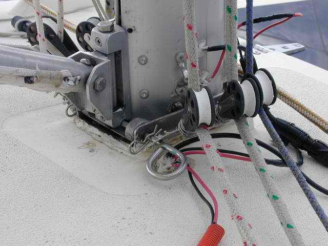
to isolate a problem without having to lower the mast. By the way,
Panache's wiring configuration through the deck (shown below) is not
elegant but it has never leaked and the balsa core is still bone dry since
I bought her in 1985.
compression bolt and the wire harness on the forward
side since the steaming light is located on the forward side. Don't consider the mast kerf as a place to install
wiring. There isn't enough room to accommodate both mast slugs and wires.
I've tried it. If you have to temporarily install a wire up the mast I
suggest taping it to an aft side. Not elegant but it works for a
while. Keep the electrical connectors at the bottom,
outside the mast, so you can maintain them and make it easier
to isolate a problem without having to lower the mast. By the way,
Panache's wiring configuration through the deck (shown below) is not
elegant but it has never leaked and the balsa core is still bone dry since
I bought her in 1985.  If the screw head strips you will have
to grind the
head off flush so you can drill or punch the stud through to reuse the hole. Another technique is to use high quality penetrating
oil with mercurochrome that will soak into the corrosion to loosen it.
I have removed some really stubborn bolts with this stuff. Be patient,
it takes time.
Don't be afraid to have another beer!
Lastly you can apply heat to loosen the screw but I'd be tempted to try a
few more shots of vinegar or penetrating oil first. Applying heat to
an aluminum mast will require a torch and a magic touch as the aluminum
conducts the heat away very quickly. The danger with a torch is that you could
liquefy the aluminum and "blow" a hole through the mast. Hardly
desirable considering the cost of the extrusion not to mention the shipping cost and delay
time to wait for a replacement!
If the screw head strips you will have
to grind the
head off flush so you can drill or punch the stud through to reuse the hole. Another technique is to use high quality penetrating
oil with mercurochrome that will soak into the corrosion to loosen it.
I have removed some really stubborn bolts with this stuff. Be patient,
it takes time.
Don't be afraid to have another beer!
Lastly you can apply heat to loosen the screw but I'd be tempted to try a
few more shots of vinegar or penetrating oil first. Applying heat to
an aluminum mast will require a torch and a magic touch as the aluminum
conducts the heat away very quickly. The danger with a torch is that you could
liquefy the aluminum and "blow" a hole through the mast. Hardly
desirable considering the cost of the extrusion not to mention the shipping cost and delay
time to wait for a replacement! 
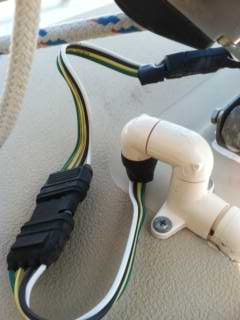
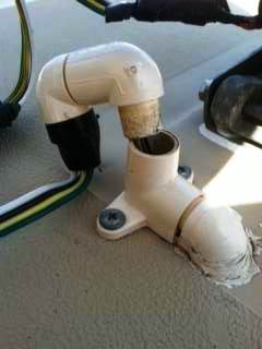 Install a fixed connector on the deck
that the mast cable can plug into. Best to install the connector
horizontally, up off the deck on a block to
keep it away from most of the water.
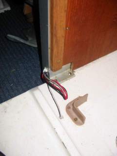
Alternatively you could install fittings on the deck as Dave Finley
has done here. The middle fitting is left loose to pull wires
through.
Install a fixed connector on the deck
that the mast cable can plug into. Best to install the connector
horizontally, up off the deck on a block to
keep it away from most of the water.
Alternatively you could install fittings on the deck as Dave Finley
has done here. The middle fitting is left loose to pull wires
through. 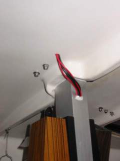
 NOTE: Leave several
feet of slack wire coiled under the floor below the head so you can move the compression post
in the future. You must move the post to remove the
port bulkhead. See
NOTE: Leave several
feet of slack wire coiled under the floor below the head so you can move the compression post
in the future. You must move the post to remove the
port bulkhead. See