|
So you're tired of being out of VHF (very high frequency) radio contact at your favourite anchorage and
have decided to install a 25 watt fixed marine radio as your primary means of communications!
This is
an excellent upgrade especially if you choose a digital selective calling (DSC) radio that has features compatible with
Coast Guard and commercial operations. Its always considerate to not interfere with commercial operation. The irony of having a fixed mount VHF radio over a low powered (1 watt) handheld radio is that many people can now reach you at your favourite anchorage, breaking the solitude you seek. The real reason of course is the reassurance that you can call for help in case of an emergency (or someone can call you) and since a sailboat is not exactly the fastest thing on the planet, you need lots of operating range to buy time. To increase the
operating range you require lots of ERP (Effective Radiated Power) which
requires a high antenna that is clear of obstructions. The
low power of a handheld radio held close to your head (which absorbs RF) doesn't
have that operating range. It works fine in a harbour
that is a few miles across but at a remote anchorage you are usually out of
range to home base. Having said all this, there is a limit to the operating range of a VHF radio when communicating over the ground.
This path is the most difficult one for a VHF signal to travel through as the propagation is limited by
line of sight (horizon) for distance, by interfering obstacles along the
ground and by electrical noise.
You can expect 20 to 30 miles from a good antenna installation. Occasionally VHF will skip (bounce off an object or atmospheric reflections) to travel a greater distance, but don't count on it for
reliable communications. For example; I once talked 500 KMs (almost line of sight) using my screw driver for an antenna
on a general mobile VHF radio, but this is in all other respects a
freak of communications. On a sailboat you are striving for dependable communications that works when you need help. This requires clean power and a first rate
electrical installation
with the antenna and associated RF ground being the most important.
WHERE TO INSTALL a FIXED MOUNT VHF RADIO - Most radios are installed where a person can read and operate
the front panel with ready
access to the microphone. It is usually possible to satisfy these ergonomic
requirements by installing the
power cables and coax in an organized fashion.
 Regardless of how tempting it may be, DON'T
mount the radio above the stove as the steam will hasten the demise of the
electronics. It sure hurts the hands to reach for the microphone through
the steam and you may need
to use the radio if the cook has an accident! Duh!
First rule in first aid, don't create a second
casualty! A VHF radio is a rather delicate thing so
mount it securely in a dry location. Regardless of how tempting it may be, DON'T
mount the radio above the stove as the steam will hasten the demise of the
electronics. It sure hurts the hands to reach for the microphone through
the steam and you may need
to use the radio if the cook has an accident! Duh!
First rule in first aid, don't create a second
casualty! A VHF radio is a rather delicate thing so
mount it securely in a dry location.
On Panache, the VHF radio, other electronics and electrics are installed to starboard and the galley is to port. This
layout keeps the cook and navigator to their respective
sides! Both are happy by not crossing
paths.
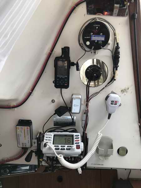
I replaced my aging Humminbird analogue VHF radio with a Uniden UM415 DSC VHF radio. Just after the 1 year warranty expired the Uniden "smoked"
itself.
So I replaced it with a
Standard Horizon Explorer
GPS
GX1700W shown at right. It is by far the superior unit.
I chose
the
white case with black keys since the contrast make the keys easy to see. I really
like this radio for its ease of use, especially the digital functions.
Many functions are executed by pushing the same key sequentially which is
really convenient, especially if you are in a hurry.
My
GPS
GX1700W radio has the standard mic equipped with PTT, channel up/down, H/L power, channels 16/9 switch. I installed my MMSI number and connected the external GPS receiver
as backup should the internal GPS fail. See Tech Tip E13 for wiring. The internal GPS feature (or external) enables
the coordinates to be sent with the DISTRESS
switch function so the Coast Guard can travel directly to your location. The selective calling feature has created a new
level of speed and privacy to send messages to a fellow boater on the lake.
All 3 of my VHF radios were mounted close to the companionway
to easily reach the microphone from the front of the cockpit.
From here I can handle a call
while scanning the water for hazards and conflicting traffic. I
added a cockpit speaker so I miss fewer calls, especially the important distress,
urgent, & safety calls plus weather alerts. A lesser
criteria (though no less urgent) is to guide the guests rowing over with libations
for the evening!
-
BULKHEAD MOUNT - Most radios are water proof, to some degree, to protect the
electronics from the high humidity on the water. Condensed humidity is far worse than rain or water spray. However, if your radio
is not water proof then mount it far enough inside the cabin to keep it sheltered, but not so far that you can't easily see the control panel.
This was an issue with my Humminbird VHF that had a small, low intensity/contrast/small font display. Pay particular attention to this last point for those
folk who wear bifocal
glasses. The radio must be mounted lower for this person so they
can focus on the display through their bifocals.
You too will get older and looking up gives you a
real strain in the neck! If the display is not back lit or poor
has low contrast
then install an LED above it. LED lighting is
very easy on the eyes and doesn't destroy your night vision.
Looking
at the photo above, the
black fixture clipped on the left side of the radio bracket is an LED
light to illuminate the power
distribution panel. The silver block above the radio house three
12VDC power outlets, the GPS and depth sounder are the next two above.
At the very top is the knot meter. The old flasher style depth
sounder died so it became a window as promised when it didn't smarten
up!
-
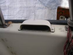
CEILING MOUNT - Another place to mount a radio is against the
ceiling just above the window. However, this
works only if the radio is short enough (front/back) so it doesn't
protrude into the companionway opening.
While it provides excellent access and audio to the cockpit, I continually bumped into my friend's
radio installed here. I found that annoying when I wanted to
brace myself in a bumpy seaway. The radio must be
water proof for weather protection. Consider gluing (Sikaflex or
Butyl rubber) the mounting bracket to the
cabin ceiling
instead of screwing it into the balsa core which would expose the wood
core. Either of these
cured adhesives is strong to support a 3 pound radio. You just have to
use a very large C clamp to hold it to the ceiling while the adhesive is curing.
My fabricated mounting bracket shown above is glued with silicon sealant and
fastened with two tiny screws (sealed) from the outside. It has never
let go.
-
MICROPHONE - Mount the microphone clip close to the companionway for easy reach
while standing in the cockpit. This way you won't drip water all
over the cabin floor just to give a quick reply. I have since modified the radio so the mic
cord exits from the right side to give me a bit more cord length so I can turn my head while talking!
 COCKPIT SPEAKER - Install a remote speaker in the cockpit so you don't miss that
important message. I have missed so many calls (and raft ups) due
to wind or outboard noise that I now consider a cockpit speaker almost
mandatory. There are better reasons of course (URGENT,
DISTRESS or SAFETY calls) but a personal call will do for now! A
cockpit speaker can also make it possible for a second set of ears to understand
a garbled or marginal signal on a better quality speaker than what the VHF
has. Consider the poor sailor calling
MAYDAY. If the speaker is installed under a cockpit seat you can
hear it through the cracks. If you want it louder
then install it under the tiller, inside a tough vinyl case with
the speaker pointed down. Best to use a membrane speaker since they
are water proof. DO NOT install it behind a
grill mounted in the cockpit foot well. The speaker cone can't stop knee
deep
water in the cockpit!
A wireless mic/speaker combination is a real nice feature when you are
locked to the tiller or
when the cook has command of the galley. I'd be the last person to
kick the cook out of the galley! Oh the joy of it all. TOP COCKPIT SPEAKER - Install a remote speaker in the cockpit so you don't miss that
important message. I have missed so many calls (and raft ups) due
to wind or outboard noise that I now consider a cockpit speaker almost
mandatory. There are better reasons of course (URGENT,
DISTRESS or SAFETY calls) but a personal call will do for now! A
cockpit speaker can also make it possible for a second set of ears to understand
a garbled or marginal signal on a better quality speaker than what the VHF
has. Consider the poor sailor calling
MAYDAY. If the speaker is installed under a cockpit seat you can
hear it through the cracks. If you want it louder
then install it under the tiller, inside a tough vinyl case with
the speaker pointed down. Best to use a membrane speaker since they
are water proof. DO NOT install it behind a
grill mounted in the cockpit foot well. The speaker cone can't stop knee
deep
water in the cockpit!
A wireless mic/speaker combination is a real nice feature when you are
locked to the tiller or
when the cook has command of the galley. I'd be the last person to
kick the cook out of the galley! Oh the joy of it all. TOP
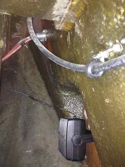
 I originally installed a cockpit speaker in the aft end of the starboard locker,
thinking it would be loud enough
with the lid closed. I
quickly discovered how well the lid mutes speech. Add some wind or run
an outboard and speech is
completely drowned out. Apparently even a
sailboat can be a noisy place! To solve this I installed the speaker
on the backing board of the outboard bracket, pointed
forward and upward to a vent
hole on top of the transom (shown here). The beauty of this
location is that it is well protected from the rain and I can hear speech,
most of the time. By crawling under the cockpit I could just reach the backing board by lying
over the cockpit drain hoses. But
this was only possible by using a drill to drive the mounting screws
(Thank you Mr. Roberts) and a temporary
plywood "bridge" to support me over the drain hoses. I originally installed a cockpit speaker in the aft end of the starboard locker,
thinking it would be loud enough
with the lid closed. I
quickly discovered how well the lid mutes speech. Add some wind or run
an outboard and speech is
completely drowned out. Apparently even a
sailboat can be a noisy place! To solve this I installed the speaker
on the backing board of the outboard bracket, pointed
forward and upward to a vent
hole on top of the transom (shown here). The beauty of this
location is that it is well protected from the rain and I can hear speech,
most of the time. By crawling under the cockpit I could just reach the backing board by lying
over the cockpit drain hoses. But
this was only possible by using a drill to drive the mounting screws
(Thank you Mr. Roberts) and a temporary
plywood "bridge" to support me over the drain hoses.
I tested the
speaker by listening to the continuous weather reports from a weather channel.
The
volume was good and the voice quality excellent while standing in the
cockpit. It was understandably more difficult to hear with the outboard running
but the volume and clarity was still good. Then I raised the port
locker seat and the sound came booming through to where it was actually too
loud. Nice when something works really well.
DC POWER -
Use the correct or larger gauge
power wire and
don't chintz out on the quality of the wire. See Tech Tip E02
for suitable wire gauge guide. Use fine stranded wire to withstand
vibration and tinned wire to prevent corrosion. Install the shortest
length of wire to the power panel, keeping a bit of slack to absorb vibration and facilitate installation. Use a ferrite bead over the power line to block RF noise. Use an inline fuse on the positive battery wire to protect against fire. Locate the fuse where it is easy to see & access. Label the fuse and power wire. It is doubtful that a fuse on the negative lead can protect the radio against a ground surge. A fuse blows too slow and since lightening has already breached the air gap to the clouds, another inch gap in a fuse is not an obstacle. For this reason I'm not installing this fuse.
When an outboard is started electrically, the surge current will
induce voltage spikes on the boat's electrical system. For this
reason you should install surge suppression like a MOV (metal oxide
varistor)
between the outboard power leads (pos & neg) to short out voltage spikes greater than 170 VDC,
thereby protecting devices connected to the system. Use a GE MOV (V36ZA80) or
equivalent. TOP
ANTENNA - If
you want the maximum possible operating range from your radio then install
the antenna at the mast head with no metallic objects around it.
Height and a clear line of sight is everything when it comes to signal
propagation and reception. It is also the safest place since you will
not be exposed to RF radiation.
 Through field tests on
Panache I've determined that a
half wave length VHF whip (about 32" long) mounted on the pushpit has an operating
range of about 5 miles (at best) and the same antenna mounted on the mast head
has a range greater
than 10 miles.
We couldn't determine the maximum operating distance since the beaches I sail
between are only 12 miles apart! Communicating to the other side of a 200'
high island covered in spruce trees is next to impossible. Through field tests on
Panache I've determined that a
half wave length VHF whip (about 32" long) mounted on the pushpit has an operating
range of about 5 miles (at best) and the same antenna mounted on the mast head
has a range greater
than 10 miles.
We couldn't determine the maximum operating distance since the beaches I sail
between are only 12 miles apart! Communicating to the other side of a 200'
high island covered in spruce trees is next to impossible.
NOTE - A bare metal VHF whip installed on a stainless steel pushpit (within
grab range) is hazardous for two reasons: an RF burn smarts your skin when the radio transmits
at 25 watts, and a person standing beside the antenna will
absorb power, which is not healthy. The closer you stand to the antenna the more
you power you absorb and the more that will affect the propagation pattern. Therefore, DO NOT install a
bare metal antenna on the pushpit.
Be wary of an LED tri-lite at the mast head. Some radiate RF noise
that can be picked up by the antenna next to
it. LED navigation lights mounted on the hull do not
have this circuitry and therefore don't transmit RF noise. You should test your
LED masthead light for RF interference by opening
the squelch on an unused channel and then switch on the light. If
you hear nothing, great, your installation is interference free.
If you hear "noise" replace the LED with one that doesn't transmit RF.
If you have AIS on board you can test interference to it by counting how
many stations you receive with the LED off. Then switch on the LED and
if you count the same number of stations, great, your installation is
interference free. If you count fewer stations, replace the LED with
one that doesn't transmit RF.
While a half wavelength whip doesn't require a ground plane to
radiate, if the radio is electrically grounded (bonded) to water it can radiate at
the optimum. Unfortunately mine wasn't bonded at the time but it still
demonstrates the point.
There are several advantages of a center fed dipole antenna over an end
fed whip antenna:
- A center fed 1/2 wavelength
dipole antenna made from copper radiates better than
a same frequency end-fed stainless steel whip, considering that the whip is generally installed without
four horizontal counterpoises to provide an artificial ground plane. Counterpoises are
necessary whenever an end fed whip is operated electrically above earth
ground. A dipole does not require a ground plane and is therefore a superior
choice on a sailboat.
-
The radiation pattern of a dipole antenna approximates the shape of a
doughnut. This is an excellent pattern to use on a sailboat that spends
continuous time
heeled over. The flatter pattern radiated from a whip is "especially
effective" at radiating your signal to outer space and into the water when heeled!
If you want a whip for your sail boat then choose a 3dB antenna since the
propagated pattern is similar to a flattened doughnut. A 6dB whip
radiates quite a flat pattern and is best suited for a power boat because it doesn't heel. What is good for the transmit performance of the antenna is
also good for the receive performance. On a sailboat you are more apt to detect that weak signal with a dipole that a whip.
- The widespread use of stainless steel for a radiating element has
nothing to do with efficiency, it is selected for its physical properties
of durability and self-supporting. Stainless steel is merely a form
of iron with a bit of nickel content to make it rust resistant.
Problem is, iron is rated as a poor RF conductor and does not radiate (low ERP)
RF well. The antenna installation
may have a nice low voltage
standing wave ratio (VSWR) but this tells you little about the resistance losses of
the antenna or the ground system. A VSWR of 1.2:1 with 75% resistance
(loss due to steel) combined with the high radiation resistance is actually poor overall performance.
Copper is
the best conductor
but only if it is corrosion free. Problem is copper oxide is a very poor RF
conductor, nearly as poor as iron, which is why corrosion protection is so important. This is
one of the reasons why
a good quality whip is coated with white vinyl and has an internal stiffener. Silver plating makes for a good RF
conductor. Silver also corrodes but silver oxide happens to be a great RF conductor. The bottom line is, iron is bad and copper or aluminum
is good. So avoid a stainless steel whip like the pox was upon it.
Instead, select a marine antenna that is centre fed (a dipole). They
are almost always made of copper and sealed to prevent corrosion.
-
For a mast head antenna, it is imperative that you install one that can operate without
a ground plane. This means using a 35" long 1/2 wave length whip or a center fed
dipole antenna. Mount the antenna on a small offset aluminum or
stainless steel plate screwed to the mast
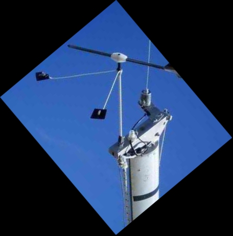
head and connect the co-ax sheath to electrical ground (water). Ensure that the Windex can turn
3600 when the wind bends the antenna towards the Windex.
I installed my Windex centrally on the aft end of the mast head so it measures a symmetrical reading on
either tack. The antenna is now installed opposite it, on a
protrusion from the
forward end of the mast head.
- I did
an ad hock test to compare my previous end fed antenna to the new center
fed antenna, operating both at 1W from the mast head. I was
pleasantly surprised with the improved performance.
- The end fed whip had a range of about 3
miles (voice quality 3x5).
- The center fed dipole had a range of 12 miles (copied 5x5). This
is the maximum distance apart on our lake. TOP
CO-AXIAL CABLE - The signal loss
through the 50 Ohm coaxial cable to a mast head mounted antenna is minimal regardless of
where you install the radio in the cabin. 35' of coax on an SJ23
just isn't long enough to worry about signal loss. However, don't kink, clamp, pinch or bend the coax tighter than its minimum
bending radius. Install coaxial cable with a stranded center conductor to survive
the flex and vibration in the mast.
Double braided
(shield) cable is
superior to
single braid. Foil with braid
is probably the best you can get, especially if it has a bleed wire to
connect to ground. Use a continuous length of
cable inside the mast so you don't have to service an intermittent
connection that you can't access. See
Tech Tip E09 to install co-ax inside the mast. It is best to
use light weight RG58AU or RG8X cable that has a minimum bending radius
of 3".
-
RG58AU coaxial cable is an
excellent compromise between minimal signal loss of (6.2dB/100'), light weight aloft in the mast
and low cost. However, there is superior light
weight coax.
- (While RG213AU is half the loss (2.8dB/100') of RG58AU, it is too
heavy aloft to use for an SJ23).
- RG400 is a better cable
at (6.2dB/100') loss with silver plated center conductor, a Teflon dielectric and double
silver plated braid shields (no dielectric between the shields).
It is highly flexible making it an excellent choice on a boat.
It won't corrode, works really well but will empty your wallet!
- Belden 9222 triax is a superior cable
at
(5dB/100') loss with a tinned copper
stranded center conductor, a polyethylene dielectric and double tinned copper braid shields (no dielectric between the shields).
It is highly flexible making it an excellent choice on a boat.
While it is excellent cable that won't corrode, it is overkill for most SJ23 applications.
-
RG8X coaxial
cable, on the other hand, is marginally thicker than RG58AU with less
loss (4.7dB/100') and is affordable. High quality RG8X is copper clad so it can't
corrode.
- Be aware that RG8X has a slightly larger diameter cable than RG58 so
requires a matching size inset reducer for a PL259 connector. You may have to special order the
connector since the cable is not as popular as it once
was. I couldn't find the correct connector so I drilled out
the cable reducer meant for a PL259 connector.
- TOOLS: RCT-2 Coax Crimp Tool ($40) or buy solder type
connectors. For stripping, use a three-level
stripper like a TerraWave Model 490947.
In 2013 I replaced my RG58AU mast cable with RG8X and in 2015 I replaced the
cabin
portion with RG8X. There was a significant reception improvement with each installation.
While the voice reception with the RG58AU was 5x5, the digital functions
were marginal. The digital functions now work flawlessly with the RG8X
cable, operating at 1W over an impressive distance of 7 KMs. TOP
CO-AXIAL CONNECTORS
-
The
PL259
antenna
connector (designed for WWII) is inferior both physically and electrically to most
other coax connectors made today. The weakness of this connector is that
it loosens with vibration and opens the ground path. Even a little bit
of looseness opens the outer conductor, creating a huge impedance mismatch
for transmitting and weakening the shielding for receiving.
I have seen so many loose PL259
connectors that it is the first thing I look for. It is amazing how
many "lousy" radios I
have "fixed" over the years by simply tightening a loose
connector. The reason why a loose connector is a major problem
is that a lot of transmitted power is reflected back to the transmitter,
with the possibility that the reflected power will damage the
transmitter (unless the radio is protected for high VSWR). In addition,
a lot of receive signal strength is lost.
This connector is inexpensive, robust and field serviceable, which is why it
is popular. To tighten a PL259 connector ensure the two teeth on the
plug mate with two recesses on the jack and tighten the barrel snug.
Check the barrel often. My VHF radio shown above is equipped with a
PL259
chassis
connector. It would be difficult to replace it with a TNC or N-Type connector, but
not impossible.
Fortunately this connector is within easy reach to check the tightness so
not much of a problem.
The TNC or N-Type connectors are far superior with their excellent impedance matching, minimal signal reflection,
minimal signal loss and maximum shielding.
They are more expensive and they stay snug with vibration. I have never seen
an N-type, BNC or a TNC connector come loose or cause a problem.
Try to avoid using a 900 adaptor though, as they attenuate more signal
than a straight through connector.
After the
co-ax cable is
installed inside the mast, attach connectors to the ends. The best
connector to use at the mast head is an N-type or TNC but you might have to use a PL259
connector just to match to
the antenna. Similarly, at the radio end, install a connector that matches to the
radio. Seal the exterior connectors with DR vulcanizing tape (black/white) to seal out water and
then cover
the DR tape with vinyl electrical tape to protect against UV rot. It is
important to protect the antenna connector very well since it is exposed to
the weather and not easily accessible for maintenance. All other lower
connectors may be protected with two wraps of electrical
tape, sufficient to last a season. This is OK on fresh
water. On salt water I would go the full moxie with vulcanizing DR and vinyl
tape. Make your last wrap going upwards so
the outside layers deflect water away, similar to shingles on a roof. Having sealed Panache's upper connector in the manner described here, I no longer remove the antenna when the mast comes down. The reinforcing bracket is substantial enough to support the antenna in the horizontal position even when travelling down the road or over winter on the trailer. TOP
RADIO
FREQUENCY (RF) GROUND The sheath of a VHF radio co-axial transmission line must be connected to a
counterpoise (at the top antenna connector) in order to
transmit/receive a signal over its maximum range. A VHF radio will
benefit only marginally from an RF ground connected through the hull to the water. It is considered overkill in
most applications unless you often sail at the edge of normal VHF reception. It
may make a difference for that operation. However, an RF ground is essential for an HF radio (SSB) to transmit/receive over
long range. With HF you want long range operation. If your SJ23 is equipped with an HF radio then read on.
Electrical grounding at RF frequencies is vastly different
from electrical grounding at DC power. In the case of an HF radio it means
0 ohms
to earth ground (not battery return or negative) at 30-150 mHz, which is quite different than
a power ground of 0
ohms at 12 VDC. The impedance of an RF ground cannot be
measured with an Ohm meter. Test the performance of the RF ground wiring by comparing the operating range with another radio or
measure it with an impedance meter.
It is generally recommended to keep your RF ground separate from your DC power
return (not ground) so an RF signal doesn't interfere (ground noise) with
the instruments, etc. There are two types of wiring for an RF ground:
-
A short run (6' or less) of flat copper strap
(1/2" copper pipe flattened or foil) connected to a copper plate immersed in
salt water. The immersed plate must have at least 144 in2 immersed in
salt water and almost double that in fresh water.
The more surface exposed to the water the better. It is considered by many that a
sharp edge conducts RF better than a flat surface which is why ground straps
attached to the outside of the hull are long and flat and equipped with longitudinal fins like a heat sink.
-
A short run (6' or less) of flat copper braid connected to several
lengths of copper foil stuck to the inside of the bilge. The foil
capacitively couples the signal to earth (water) at very low impedance,
thereby achieving a ground. The bottom of the settee lockers are a
great place to install the foil but the foil must be protected from items
stored there. I think a 6" wide false flat floor installed at the bottom
of the locker would be perfect. Make it from 1/4" pressure treated
plywood.
NOTE - In some installations a good lightning ground may also be a good RF
ground, serving a dual purpose of life protection and optimal RF
performance. Problem is when the lightning ground is conducting a
charge from the surrounding air to the water it might carry enough current
to damage expensive electronics. Usually an RF ground is wired with
small gauge wire to carry minimal current while a lightning ground is wired
with 0:0 wire to carry an ungodly amount of current. Therefore I
recommend separating the RF and lightning grounds to simplify maintenance,
trouble shooting and potential loss.
GENERAL
GUIDELINES FOR A GOOD RF GROUND - Be aware that an RF ground is not really required for a weekend sail since you generally
stay within VHF range. However, if you
decide to sail to the "working edge" of the VHF operating range you should consider installing an RF ground
to improve reception there. It is
more effective on salt water than on fresh which why you can talk further
over salt water.
- RF CONDUCTIVITY - RF conductivity is not the same as DC conductivity. Don’t confuse your battery return or hazard ground
wiring (equipment chassis) with
your RF ground. The RF ground is required for the ANTENNA
circuit. The hazard ground on DC circuits is NOT intended to handle RF. While many boats connect these together successfully, RF can
interfere with instruments or other equipment via the DC power return
wire (ground). It is always best to have separate
RF and DC safety grounds.
-
 FOIL -
Install long 4" wide strips of copper foil on the inside
surface of a fibreglass hull. It
capacitively couples the RF signal to the seawater and generally makes a
good RF ground system. This is NOT a lightning or a DC safety ground. FOIL -
Install long 4" wide strips of copper foil on the inside
surface of a fibreglass hull. It
capacitively couples the RF signal to the seawater and generally makes a
good RF ground system. This is NOT a lightning or a DC safety ground.
- RF GROUND PLATE - A Dynaplate, or other external metallic device meant to connect your RF ground
to salt water is an excellent RF ground. Connect the
thru-hulls
and other metal fittings to it with short, direct, flat copper
straps. Include the outboard, fuel and water tanks (if metal), the keel,
and any other piece of metal of significant size. If the mast is
bonded to this immersed plate it should also eliminate 80% of your chances of
being struck by lighting.
- KEEL
- A
lead keel
immersed in salt water is an excellent RF ground. If the lead ballast is
encapsulated in fibreglass like
an SJ23, it is
difficult to make a good
connection to the ballast. In this case you must drill through the
fibreglass sole to bond a ground strap directly to the lead using a lag bolt. Make
the hole large enough to easily inspect the cavity for water intrusion.
Seal the metal surfaces with water proof grease to prevent
corrosion.
- CONNECTIONS - Connecting your RF ground can be tricky. Keep your
ground straps as short as possible, less than 6'. To make a
connection, polish the end of the copper strap, coat it with a water proof
grease to prevent corrosion, then tighten the silica bronze
bolt/washers/nut combo. ALWAYS use the same metal. Don't just
tighten the nut. Torque it to spec to ensure uniform pressure
on the washer (minimal electrical resistance) around the bolt.
- MAINTENANCE - A ground plate is only effective if you maintain it
properly. Since a salt water environment is very
corrosive all electrical connections must be inspected regularly and the
ground plate in the water must be CLEANED at least every 3 months. If you have an antenna tuner in
your system, it will hide slow
degradations in your antenna or ground system until it can no longer
compensate for them. You may be able to operate for a long time while
your fittings corrode and then discover you can’t operate at all. It will
seem sudden, but the problem grew gradually! However, transmitting the radio can clean off corrosion on the ground plate. This is one of those times it pays to be chatty on the radio.
- TESTING - Often people will use a volt-ohmmeter to measure the
resistance of
a ground strap and declare it good because there is little or no
resistance. While 0 ohms continuity is the first step, it is the
impedance that must be measured at 150 MHz. A
difficult thing to do. A useful test of the quality of your ground is to temporarily lay out several long
wires on deck with one wire over the side to connect to water. Connect the wires to the RF ground connection on your antenna tuner or
co-ax. If the signal stays the same then your RF ground is working
fine. If the signal gets worse when you remove these temporary
wires, your RF grounding system needs repair work. Be prepared to adjust your RF ground as you
test it and remember that it will degrade over time.
Overall, there are probably as many different ways to create a good RF ground as there are people giving advice about
it, myself among
them. What works on one boat
may not work well on another. Shown
here is a drawing of the technique I developed to bond a co-ax cable ground to
the mast.
The mast is also bonded to the compression post which in turn is currently
grounded to water via the outboard leg. Good article on RF grounding TOP
EMERGENCY VHF ANTENNA
 It's always a good idea to have an emergency antenna just in case the
big stick decides
to fall down and you want to cancel your theatre tickets. On the
other hand if you are the
committee boat and two people need to talk
to different boats at the same time, use the emergency antenna. Failing that it can always be
used as a perfectly good AM/FM antenna. It's always a good idea to have an emergency antenna just in case the
big stick decides
to fall down and you want to cancel your theatre tickets. On the
other hand if you are the
committee boat and two people need to talk
to different boats at the same time, use the emergency antenna. Failing that it can always be
used as a perfectly good AM/FM antenna.
EMERGENCY RUBBER DUCKY -
A "rubber ducky" (flexible rubber) antenna can be more
effective as an emergency antenna if it is hoisted up the mast using a 30'
long extension of RG58AU coax cable equipped with PL259 connectors.
This combination works for the ship radio. If you want to connect a hand held radio
instead then carry a
PL259
(female)
to TNC
(male) adapter since most hand held radios are equipped with a TNC antenna connector.
Store the adapter and coil of co-ax in a sealed plastic bag to keep
it corrosion free. The reason for the 30'
length is to raise the antenna as high as possible on a whisker pole or so you can
talk from inside the cabin with the antenna hoisted. Remember, height
is everything
when it comes to RF propagation, especially with a poor antenna like a
"rubber ducky."
EMERGENCY DIPOLE
ANTENNA
-
My emergency antenna is a homemade center fed dipole that can really improve the
performance of a 1W handheld radio.
The antenna is housed inside a PVC tube for electrical insulation and weather
protection. The mounting clamp at the bottom fits on the pushpit.
See diagram at right.
Strip away 47.875 cm of the co-ax vinyl jacket and shield to reveal
the insulated center conductor. Seal the end of the center conductor
and the end of the shield with marine silicon sealant to prevent corrosion.
Then slip five ferrite chokes over the vinyl outer jacket, positioning them
47.875 cm from the end of the braid. The exposed inner conductor
defines the length of the top element and the ferrite chokes define the
electrical end of the bottom element. They are the same length.
Lock the ferrites in place with a light dab of silicon sealant. Slip
the antenna inside a stiff 1/2" ID white PVC or fibreglass tube that is 1
meter long. Cap the top, leave a tiny vent hole at the bottom and add
a mounting clamp there as well. Extend the co-ax cable to the fixed
mount radio or to a hand held radio, leaving several feet of slack for freedom of movement. Alternatively,
hoist it to the spreaders or higher, keeping it away from the mast. I intend
to install my alternate antenna on the pushpit using it primarily as an
AM/FM antenna.
NOTE - Don't install a bare metal whip on
the pushpit or where somebody can touch it. If you touch the whip while the radio is transmitting you can
get a very nasty RF burn, especially if the cockpit is wet. Use an insulated whip.
It is not too difficult to make an emergency center fed
dipole
antenna suitable for a sailboat.
All you need is some 50 Ohm co-ax cable (RG8X or RG58AU), a choke made by
coiling the co-ax, a rigid PVC tube to house the dipole and a suitable co-ax connector to match your radio.
Total length of the antenna in meters is, L=147/frequency
in MHz.
For example, a channel 16 dipole (156.8 MHz): 147/156.8 = .9375
M.
Each element of the
dipole calculates to be 46.875 cm. (1"=2.54cm).
To tune the impedance of the antenna:
-
Connect an inline RF wattmeter and a dummy load to the radio
and measure the transmit power on channel 16.
-
Remove the dummy load and
connect the antenna using a 6" co-ax cable to the watt meter. The wattmeter needs to be very close to the antenna without being inside the
radiated RF.
-
Adjust the lengths of the
two elements while measuring the reflected power on the watt meter.
-
Either cut or fold over the center conductor (radiating
element) so the two elements are equal length and slide the ferrite choke
for minimum reflected power and maximum forward power at the critical
length.
-
You should have nearly the same forward power as your original
measurement into the dummy load.
PRIMARY
CENTER FED DIPOLE ANTENNA
- You
can make a primary mast head antenna from an aluminum tube and a rigid rod
if the rod is electrically isolated from the tube and the tube is electrically isolated from the mast when mounted.
This antenna design has less wind resistance than the equivalent antenna
installed inside a PVC tube as shown above. The rod fits securely
inside a phenolic insert set into the top of the aluminum tube. Cut
the rigid rod and the aluminum tube 47.875 cm long. The co-ax center
conductor connects to the bottom of the rod and the shield connects to the
top of the aluminum tube.
 Marine VHF
radio transmission is
vertically polarized for omni-directional propagation so mount the
antenna vertical with the center conductor pointing up to keep the rain out. At left is
a design I developed (but never implemented) for mounting a 1/2" vinyl supporting tube
to house an antenna mounted on top of
a spreader.
The T configuration should prevent chafe and snagging things. The
co-ax cable exists near the bottom of the vertical tube. It is fastened along the
bottom (outside)
of the spreader and enters the mast just below the spreader. The co-ax cable
then exits at the bottom of the mast where it terminates in a PL259
connector fastened to a bulkhead connector. (See sketch above) The outside thread
(ground) of the adapter is bonded to the electrically grounded mast to connect to the
lightning ground. The co-ax
cable fed up through the deck in connected to the
bottom end of a bulkhead connector. Ideally there is an antenna tuner
between the antenna and the radio to correct any impedance mismatch of the antenna
regardless of which channel (frequency) you transmit on but is generally not
required for VHF.
The balanced 50 ohm impedance of the dipole should also be matched to the
unbalanced impedance of the radio using a balun transformer. This is
not as important for receiving as it is for transmitting. The mismatch
without the transformer will reduce the sensitivity a bit. If the
antenna is installed on a spreader then the radiation pattern will likely
have a notch (RF shadow) caused by the metal mast. This location it is
a good compromise between reasonable height above water and in the better
position so as not to be the magnet for a lightning strike. Probably
the best use for the mast top is a lightning rod or a tri-light. TOP Marine VHF
radio transmission is
vertically polarized for omni-directional propagation so mount the
antenna vertical with the center conductor pointing up to keep the rain out. At left is
a design I developed (but never implemented) for mounting a 1/2" vinyl supporting tube
to house an antenna mounted on top of
a spreader.
The T configuration should prevent chafe and snagging things. The
co-ax cable exists near the bottom of the vertical tube. It is fastened along the
bottom (outside)
of the spreader and enters the mast just below the spreader. The co-ax cable
then exits at the bottom of the mast where it terminates in a PL259
connector fastened to a bulkhead connector. (See sketch above) The outside thread
(ground) of the adapter is bonded to the electrically grounded mast to connect to the
lightning ground. The co-ax
cable fed up through the deck in connected to the
bottom end of a bulkhead connector. Ideally there is an antenna tuner
between the antenna and the radio to correct any impedance mismatch of the antenna
regardless of which channel (frequency) you transmit on but is generally not
required for VHF.
The balanced 50 ohm impedance of the dipole should also be matched to the
unbalanced impedance of the radio using a balun transformer. This is
not as important for receiving as it is for transmitting. The mismatch
without the transformer will reduce the sensitivity a bit. If the
antenna is installed on a spreader then the radiation pattern will likely
have a notch (RF shadow) caused by the metal mast. This location it is
a good compromise between reasonable height above water and in the better
position so as not to be the magnet for a lightning strike. Probably
the best use for the mast top is a lightning rod or a tri-light. TOP
PERFORMANCE
TESTING THE OVERALL INSTALLATION - Ever wonder if your installation is working?
-
You can temporarily connect an inline watt meter to the coax cable to determine if the
antenna is terminated correctly. All things being correct the meter should read
very little reflected power and 100% forward power, about 25 watts or equal to the
rating of your radio.
- Use your handheld
VHF radio to make an operational test; IE: talk to yourself on an idle channel,
not 16 or 9!
- Request a radio check from
a fellow boater. Keep in mind that the other boat may have a poor
installation which will affect the test. Remember to ask for their location to get some idea of the
distance.
If you can talk to somebody who is 25 miles away then your system is in
good condition. Switch between high power and low power.
Its
amazing how many people will "piggy back" on your radio check to
confirm their operation. Don't let it bother you. The more people who check
their radio the safer it is for all. Don't be shy to help another guy
test his radio.
- Listen
to radio traffic to determine the location of other operators to determine your operating range.
Its a pretty safe bet that if you can hear a distant station then your
antenna and co-ax installation is good. Just don't expect your radio to reach a
distant station as the reciprocal rule of distance doesn't always apply.
You may be receiving them via RF skip. The physics can be
complicated and is beyond this Tech Tip to explain.
- Don't be surprised that the
Coast Guard signal comes booming in where you don't expect it. Their shore radio installations are
professionally maintained and their sites are usually located on high ground
equipped with high powered radios. In some cases they use high gain directional
antennas or multiple sites to direct their signal to you.
After all, communications is
their lifeline during a rescue and they MUST contact you to find you.
- TIP:
Remember to transmit
on low power FIRST so you don't interfere with a distant
radio. Always use low power in a harbour. Go to high power when the
distance approaches 5 miles or when there is an obstacle between
the two of you.
- A digital call is generally 20% more efficient (greater distance) than an audio call and it usually comes with confirmation. TOP
|