|
SJ23 Tech Tip F09, (Updated 2023-06-09) Art Brown, Bret Hart & Bob Schimmel |
|||||||||||||||||||||||||
|
Split
Backstay Adjuster Install -
An 8:1 factory design that is easy to operate. |
|||||||||||||||||||||||||
 Some sailors consider a backstay adjuster a "go fast" gadget for racing while furler manufacturers consider it "essential" for smooth operation of their roller furler. There is a third category I'd like to call, "protection." In 2015 two of us motored a C&C 27 down the lake in really shitty weather. The temperature was just above freezing, with very steep 4' waves in which the aging Autohelm 300 was pushed off course in the stronger puffs. The owner decided to tighten
the backstay adjuster to save the mast from shock loading the standing rigging. There was a good chance of breaking the stick.
Tightening the standing rigging like this to save it was a first for me. Like I said, "Really shitty weather." Some sailors consider a backstay adjuster a "go fast" gadget for racing while furler manufacturers consider it "essential" for smooth operation of their roller furler. There is a third category I'd like to call, "protection." In 2015 two of us motored a C&C 27 down the lake in really shitty weather. The temperature was just above freezing, with very steep 4' waves in which the aging Autohelm 300 was pushed off course in the stronger puffs. The owner decided to tighten
the backstay adjuster to save the mast from shock loading the standing rigging. There was a good chance of breaking the stick.
Tightening the standing rigging like this to save it was a first for me. Like I said, "Really shitty weather."
So you think you don't need a backstay adjuster because you only cruise your SJ23? Well think again.
Don't be tempted to tighten the
forestay of a mast head rig to solve this problem. The
backstay can tighten the forestay with less force due to a slightly more
advantageous angle to the mast head
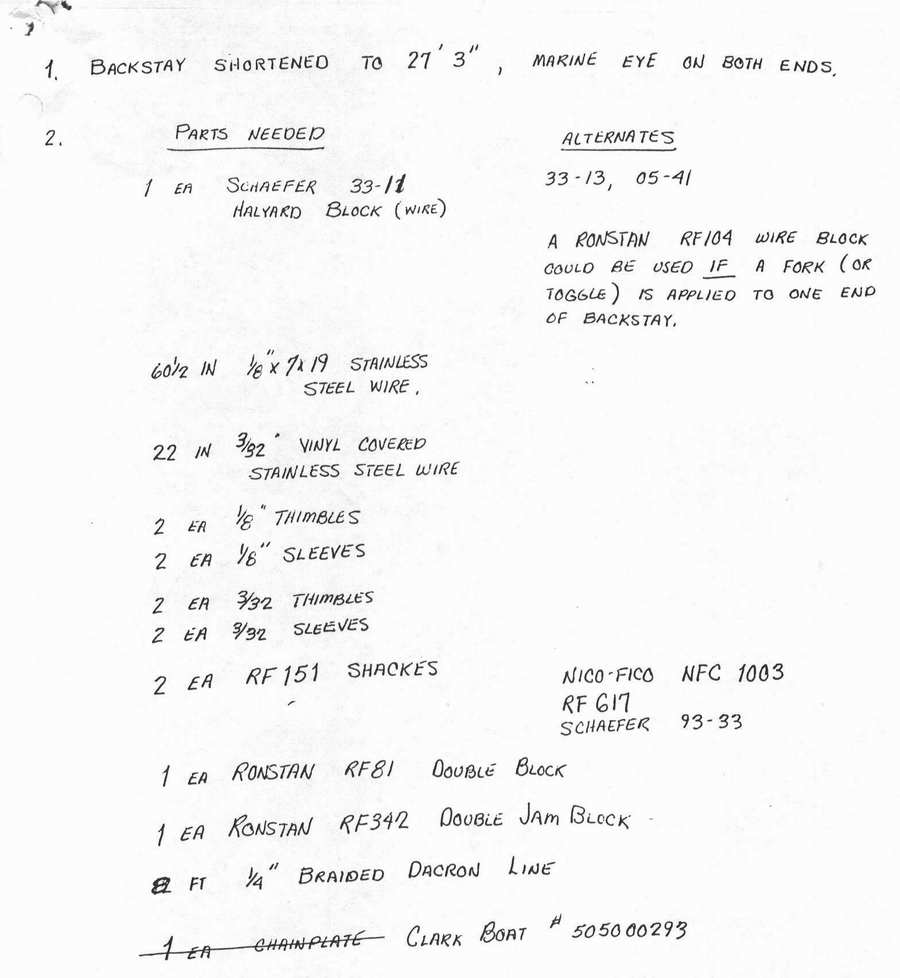
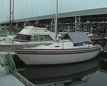
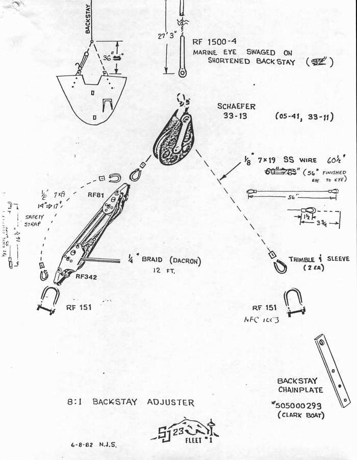
(greater mechanical advantage). A tightened forestay relates to approximately 1/2 knot of extra upwind speed. Not too shabby! Shown above is a factory 8:1 backstay adjuster kit that was sold by Clark Boats to those SJ23 sailors wanting to do some racing. There was no roller furling in the late 1970s. This factory design is quick to set and easy to release. Some SJ23s were equipped with this option at the factory but most were installed afterwards by the owner, including the second chain plate. The part numbers shown are early 1980s vintage so you will have to update them to equivalent parts today. Listed below are the parts used for Panache. Thanks to Art Brown for preserving this document
from the Seattle SJ23 Club.
|
|||||||||||||||||||||||||
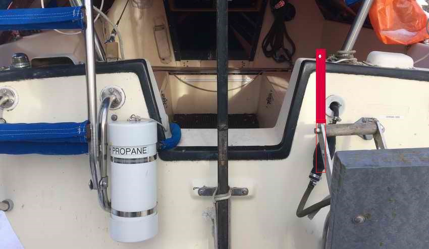
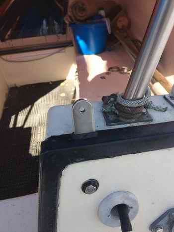
Panache SECOND CHAIN PLATE, (2018-04) - First thing first, the second chain plate must be installed. I've been wanting to do this job for a long time but held off because the cockpit drain tubes blocked access to the starboard side of the transom. I considered building a temporary false floor over the tubes but rejected it because it involved too many trips in and out of the hull. It was too cold to twist off the port drain tube so I cut it off. (Having a knife handy can be dangerous). But I still couldn't quite reach the top of the starboard transom. So I used an offset box end wrench with a dab of butyl rubber on the nut to hold it against the bolt so my buddy could start threading it from the outside. (I never dropped a nut this time and wish the technique always worked this well!). The alternative was to install a 6" inspection port in the aft end of the cockpit as per Tech Tip D03. Something I didn't want to do at the time.
|
|||||||||||||||||||||||||
|
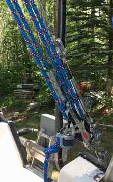
Panache BACKSTAY ADJUSTER for ROLLER FURLING, (2018-04) - With the Schaefer CF-500 roller furling installed on Panache (Tech Tip F10) the forestay length was fixed when the turnbuckle was locked against the backstay to restore the rake of the mast. Fixed length because the forestay turnbuckle is now inaccessible inside the torque tube of the furler. This means the forestay tension can only be adjusted by the backstay turnbuckle or a tensioner. The thread of a standard turnbuckle (IE: factory single backstay) is not designed for continual adjustment under variable sailing loads. It will eventually fail with catastrophic results. So that leaves a backstay adjuster which is recommended by all roller furling manufacturers since a furler rotates easier on a tight, straight forestay. Easy rolling is really important when you need to furl or roll up a jib in a gathering breeze. The rig tension can be relaxed at the dock, which many manufacturers recommend to prolong the life of the standing rigging. The halyard can also be relaxed to save the swivel bearing and the jib luff.
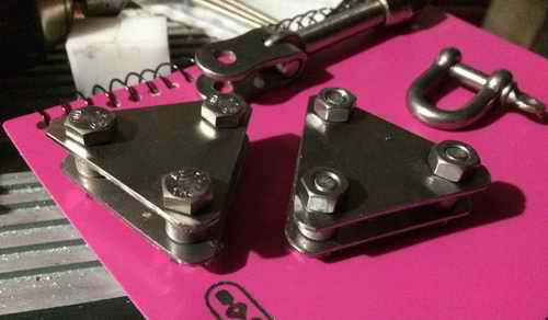
I modified the backstay adjuster slightly by adding a turnbuckle to the bottom of the safety wire to set the minimum rig tension. This way the mast is not solely reliant on the block and tackle for support and should therefore be as dependable as a squeeze adjuster. The safety wire is connected through two custom fabricated triangle plates to which the 4:1 block and tackle is connected in parallel. With the turnbuckle parallel to the block and tackle I can remove the barrel and ease the adjuster line out to the stopper knot, letting the mast lean 2" forward from its normal angle. This creates the required slack to pin the forestay while stepping the mast. The stopper knot is a safety feature that limits the forward movement making this technique perfectly safe.
- Wrap the wire tight around a thimble. Match the thimble size to the wire bending radius to maintain strength. ______________________________________________ 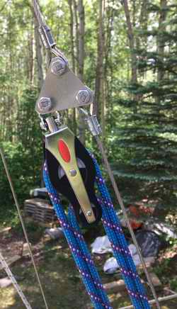 SAFETY WIRE with BLOCK & TACKLE
- A good feature of this backstay adjuster is the
1/8" 7x19 SS safety wire
that
supports the mast in case the adjuster line releases from the cam cleats or breaks. I reverse engineered this design by considering the safety wire
as the primary support and the block and tackle
the secondary support. This would achieve a safety factor similar to a squeeze
adjuster, provided the rest stays intact. I don't like compromising safety, strength and
endurance for a "go fast" gadget. SAFETY WIRE with BLOCK & TACKLE
- A good feature of this backstay adjuster is the
1/8" 7x19 SS safety wire
that
supports the mast in case the adjuster line releases from the cam cleats or breaks. I reverse engineered this design by considering the safety wire
as the primary support and the block and tackle
the secondary support. This would achieve a safety factor similar to a squeeze
adjuster, provided the rest stays intact. I don't like compromising safety, strength and
endurance for a "go fast" gadget.
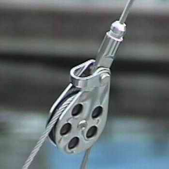
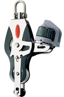
RONSTAN Block Smart Feature - A sliding post on these fiddle blocks can be pushed to one of two stop detents to fix the swivel pin at 00, 900 or disengaged for free turn. No tool required. Its perfect for this application. These are set to full swivel.
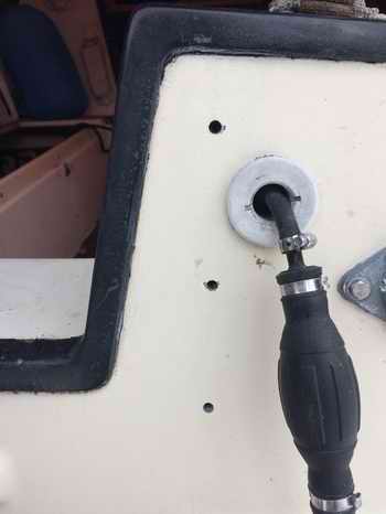
NOTE - When releasing the
control line DON'T just let it go. This shock unloading,
plus forgetting to tie a stopper knot, is a
recipe for loosing the mast. Instead, ease the line out
with your hand for a soft landing at the stopper knot.
TEMPORARY REPAIR
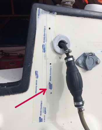
- In the repair that followed, each single sleeve was cut off and temporarily temporarily replaced with two sleeves as recommended by Nicopress. Doubling the sleeves shortened the wire 3" so I added a SS strap to the starboard chain plate to fill the gap. This allowed me to continue sailing for the season without having to lower the mast. |
|||||||||||||||||||||||||
|
|||||||||||||||||||||||||
FIELD OBSERVATIONS of BACKSTAY ADJUSTER
-
At the end of the first season of use I now feel it is fair to judge the performance of this
backstay adjuster.
I installed a lot of things at the same
time and had some growing pains as a result, hence the delay.
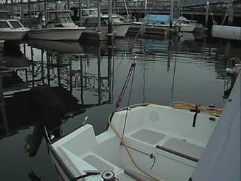
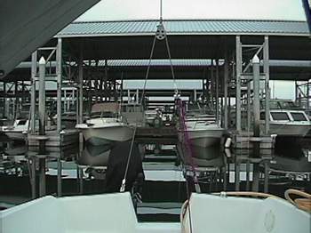
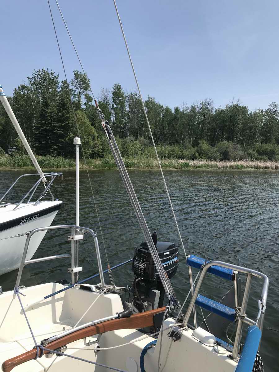
Keeping in mind that Panache has a split pushpit, I have noticed the following
since the installation:
|
|||||||||||||||||||||||||
| Q - "I do
a little racing now and then and I noticed that I have some head stay sag
that is affecting my upwind performance. I've thought about installing a backstay adjuster and would probably use the
factory design you've posted
here. I wonder how well this would
work with a mast head rig and deck stepped mast. It seems to me it
could put a lot of extra downward force on the deck and compression post
and I wonder if you see it as a potential problem more than a benefit. I
have a friend who has a deck stepped fractional rig and the pull results in bend rather than a downward force. I have seen some
SJ23's with adjustable backstays, in a split configuration, and it didn't
look like the deck was damaged or anything so I wonder what the factory
design looks like. I tend to worry
about the small things too much so maybe it's only a quick answer for you! Your
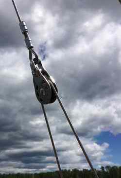
advice is greatly appreciated." Bret. A - "If you want to be successful in racing or fast cruising, you must have a backstay adjuster to tension the forestay. It's one of the best gadgets for pointing upwind as high as possible. For downwind sailing you slack it off and away you go with fuller sails to grab the wind. This adjuster works even better on the SJ7.7 with its fractional rig. To understand this you have to realize the mechanical advantage that makes it possible to bend a fractional rigged mast with less effort. On a mast head rig it is less beneficial, but still useful. I added one to my previous Macgregor Venture 222 with mast head rig and it helped a lot going upwind. I also added a baby stay adjuster that could flatten the mainsail by bending the mast forward. A baby stay can bend a mast very easily so use a stopper knot to limit the pull. Don't overdo it." If I were to install a backstay adjuster on an SJ23, I'd install the Clark design shown above. An adjuster can increase the loading on the bottom of the mast, as you suggest, but this force is NOTHING compared to the load when the boat is knocked down on her side. Panache is one of the earliest hulls out of the mold and she survived two knock downs in 2000 without damaging the original standing rigging. So don't worry about damaging the deck. The forces are well distributed through the tabernacle and supported by the compression post under it. If you are concerned about the deck see Tech Tip F03." Bob. Construction - Bret modified the original Clark design somewhat
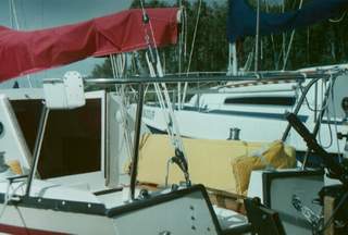
by installing a new 5/32" backstay with Sta-Lok fittings for the wire block. This is the smallest wire size a Sta-Lok can fit
to. He ran the free end of the control line to a
cam cleat so it is easy for the helmsman to pull or release the line when heeling. Below are the photos of his installation on Cosmo.
|
|||||||||||||||||||||||||
|
|||||||||||||||||||||||||
|
For ultimate strength and peace of mind the split backstay adjuster system that squeezes the two split wires together with a couple of wire blocks is the strongest and most dependable. While there is enough space on the top of the transom to fit a 2" wide pad eye just inside each chain plate, the 2 pad eyes must be reinforced from below to offset a potentially weak fibreglass joint under the black corner moulding. It would be a daunting task to fit an angle reinforcement plate and tighten the nuts from below, considering the tight space. In any case, the squeezer design works best when the 2 split wires are about 300 apart which is impossible to install over the narrow spacing of the SJ23 transom chain plates. To give this design a fighting chance it should have ball bearing blocks to roll along the 2 bottom wires. For these reasons I rejected this system. Just thought you should know. NOTE - A backstay adjuster is not cheap since the hardware has to be strong enough to replace the bottom 5' of the backstay. Verify the strength of the blocks, etc when you buy. The two systems discussed here cost about the same with each having its pros and cons.
See Tech Tip F10.
|
|||||||||||||||||||||||||
|
Return to Tech Tip Index. . . . . . . . . . . . . . . Have a Question? |
|||||||||||||||||||||||||