|
REPLACE FACTORY SHROUDS, (2020-21).
5/32" WIRE -
During the summer of 2020 I
discovered a broken strand on one of Panache's lower shrouds.
Given the fact that the factory original 1/8" rigging was 45 years old, it was prudent to
replace all the shrouds. To be consistent with the forestay I chose
5/32" wire. The extra bit of weight
for the larger 5/32" wire is insignificant as the 1/8" factory shrouds weigh 3.4 pounds
and the 5/32" shrouds weigh ~4.5 pounds, (less turnbuckles). Wow that's a mere 1.1 lbs more! For reference, the 100' of 5/32" wire I bought weighs 5.7 pounds.
-
It is cheaper and easier to replace all four shrouds at the same time than to do the job piece meal over several years. Its also smarter to
replace the standing rigging now than to wait till the
mast drops!
- Since the thread of the factory original 1/4" turnbuckles was too sloppy for my liking, I installed new 5/16" open body turnbuckles equipped with stronger drop forged T-bolts. Then I used Velcro lock pins to prevent movement in each turnbuckle.
- I seriously considered Dyneema standing rigging but rejected tying the frapping knot on the launching ramp as taking too long, especially during my cold October haul outs when knots could be frozen. I still can't understand why replacing the knot with a SS turnbuckle was not recommended at the time, despite the fact that some people did so. Then there is the problem of loosening the shrouds 3/8" for stepping the mast. Its a lot of knot work. I'm glad that somebody did this conversion on an SJ23 though. See Greg's installation in Tech Tip F34b.
-
In future I may lighten the running rigging with Dyneema halyards but that is for another Tech Tip.
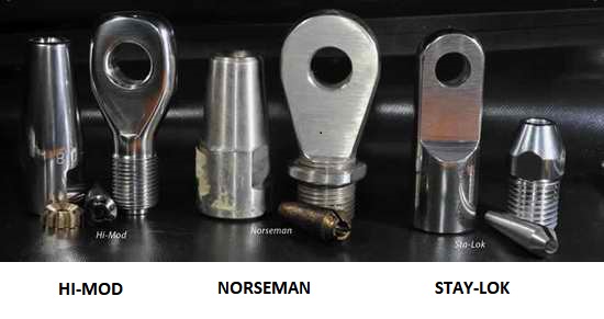 MECHANICAL
TERMINALS - I could have replaced the worn 1/8" rigging with new
swaged wires from
San Juan Sailboats
for a simple bolt on solution but chose to install new
wire with mechanical terminals from Rigging
Only. See list of parts below.
Mechanical terminals are basically corrosion resistant if they are
filled with the correct sealant to keep water and air out. The terminals have matching scantlings to
prevent point loading, their quality of machining prevents failure
(fatigue resistant), their strength is > to the wire they terminate
and they can be reused with a new wedge if installed correctly. MECHANICAL
TERMINALS - I could have replaced the worn 1/8" rigging with new
swaged wires from
San Juan Sailboats
for a simple bolt on solution but chose to install new
wire with mechanical terminals from Rigging
Only. See list of parts below.
Mechanical terminals are basically corrosion resistant if they are
filled with the correct sealant to keep water and air out. The terminals have matching scantlings to
prevent point loading, their quality of machining prevents failure
(fatigue resistant), their strength is > to the wire they terminate
and they can be reused with a new wedge if installed correctly.
Here are a few points to note:
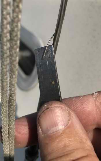
UNBALANCED WIRE - If the core of the wire withdraws a bit after it is cut, it indicates the strands were not balanced when the wire was made. If use it tends to put more load on the core, lowering the breaking strength. It also makes it difficult to assemble the terminal.
- Exchange the wire for new. 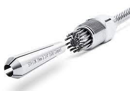 UNEVEN STRAND ENDS - Uneven length of outer strands makes it hard to form them evenly over the wedge and they are likely to snag. The outside strands MUST be the same length to contact the former at the same time. UNEVEN STRAND ENDS - Uneven length of outer strands makes it hard to form them evenly over the wedge and they are likely to snag. The outside strands MUST be the same length to contact the former at the same time.
- Use a hacksaw instead of shears to cut the wire and file the burrs off the ends to make them smooth for equal forming.
TWISTED OUTER STRANDS - The outer strands must form over the wedge in an even pattern for uniform load distribution. Twisted strands are impossible to form over the wedge.
- Ensure the strands are straight and evenly spaced prior to forming.
- Never let a strand slip into the slot of a wedge as this prevents the wedge from compressing around the core so it can't take a load. CORE SHOW - Too much or too little core showing past the wedge can compromise the terminal efficiency.
- Position the wedge on the core exactly where the manufacturer states so the strands are formed over the wedge correctly to distribute the load equally among all strands. WRONG WEDGE - Ensure you have the correct matching size wedge designed for the terminal and the wire.
- The wrong size wedge cannot grip the wire and can be pulled out of the terminal. GALLING - Use Loctite on the thread as a lubricant to prevent galling during assembly. Also use it on the former so it turns freely inside during assembly. Its amazingly easy to literally weld the terminal parts together by dry tightening.
- After tightening, the Loctite becomes an adhesive that prevents loosening. DAMAGED THREAD - If the thread rumbles (squeaking is OK) it can lead to galling. Keep it clean.
- Exchange the terminal for one with smooth thread. SEALANT - Sta-Lok & Norseman recommend polysulfide or polyurethane sealant that is free of acetylsalicylic acid (vinegar smell) to completely fill the inside to prevent corrosion.
- It must ooze out of the connector when tightening it. OVER TIGHTENING - When tightening, run things firmly home.
- Once you feel solid resistance there is no point is adding more than 1/4 turn.
The following links demonstrate the
assembly of a terminal better than my text
can;
HINT - Use
your fatigued shroud with turnbuckle as a template for making a new
shroud to the same overall length. Also see
Tech Tip
H02 for specs.
TOP
|
FABRICATE LOWER 5/32" SHROUDS, (Fall 2020).
As usual
with other jobs on Panache there were a few surprises with this
job too. If you ever
thought you could set the mast athwartship to the hull by measuring the
height of the
shroud turnbuckles, think again (See Fig 2).
The length of
Panache's lower factory shrouds differed by 1/2". Fortunately this
was
within range of the
turnbuckles
to adjust and thankfully I never used this technique sugested by a sailing buddy.
|
|
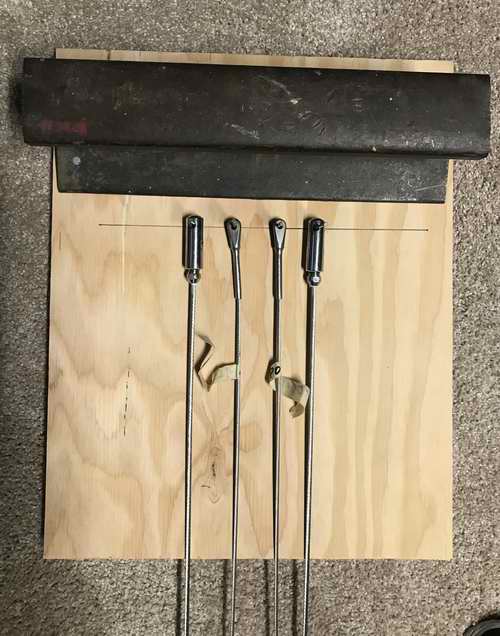
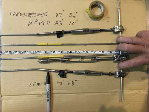
Fig 1, LINE UP THE TOPS - The length of
the new shrouds had to
be measured accurately and its best to use a board like this. It never moved with a section of
railroad track weighing it down. The worn swaged shrouds are on the inside and the new shrouds with Sta-Lok forks (top terminal) were set on the outside.
|
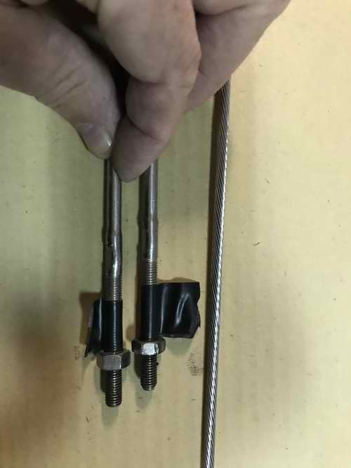
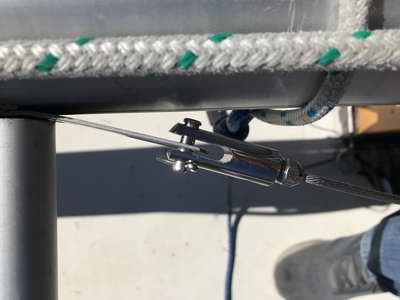
Fig 2, MEASURE THE LENGTHS - The worn
factory shrouds
were tensioned to accurately measure their lengths. Always measure with a 50' tape. "And you thought the shrouds would be equal length? Guess again, 1/2"
difference!"
|
|
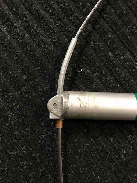
Fig 3, CUT THE WIRE TO LENGTH - The Sharpie points to how far the new 5/32" wire goes inside the Sta-Lok terminal and is lined up with the dot that marks where the 5/32" wire is to be cut. This measurement was determined with all four wires tensioned to laser straight and
turnbuckles screwed in 1/3.
NOTE - The turnbuckle toggle pins
were lined
up for equal length, keeping in mind there has to be
sufficient thread to release the turnbuckles 3/8" to step the
mast with sufficient thread to tension the
rig.
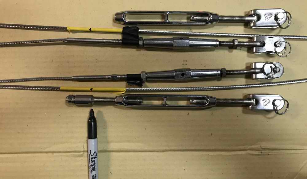
To make most efficient use of the wire I installed a Sta-Lok fork on each end of the coil and the piece left over from the middle was for the rest of the shrouds. This plan worked. Note the wire going off the edge of the cardboard to the right.
|
|
 Fig
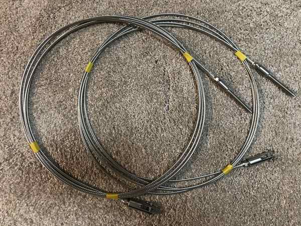
4, ASSEMBLED LOWER SHROUDS - The lower shrouds were fabricated
in Fall 2020 and are ready to
install on
the mast. The turnbuckles aren't on yet because they would bend
the wire while stored this tight in the box over winter. Fig
4, ASSEMBLED LOWER SHROUDS - The lower shrouds were fabricated
in Fall 2020 and are ready to
install on
the mast. The turnbuckles aren't on yet because they would bend
the wire while stored this tight in the box over winter. The 5/16" toggle pins
were "thickened" to 3/8" with a snug fitting SS
tube
(1/16" thick wall) slipped over
each pin. This eliminates point loading of the turnbuckle pins in the
3/8" chain plate holes. A bit of a pain to do but given
the late discovery, what the hell.
"I should have
ordered the turnbuckles with 3/8" pins. A slight oversight when
ordering them." NOTE - "Out of curiosity
I once dismantled a Sta-Lok
terminal that was compressed against a crooked former. It
took 4 hours of delicate picking to remove the wedge, former and strands from inside, they were compressed
that tight. Its safe to say the terminal was pretty well a solid mass of metal.
Despite that, I still wouldn't trust it to support a load bearing
structure, let alone a mast. But, the terminal was reused with new wedge and former in another
installation with no problem. Damn good hardware."
|
TOP
|
FABRICATE UPPER 5/32" SHROUDS, (Fall 2020).
Panache's
factory upper
shrouds differed in length by 1/8" which is no big deal.
However, they were shorter than spec by 1" which is a big deal. See
Tech
Tip H02.
After having removed all the turnbuckles I forgot to mark which were for the
upper & lower shrouds. Grrr. This presented a
problem. Given these two unknowns I decided to finalize the length of the
new shrouds with the mast standing
in the Spring of 2021
as it is the surest way to determine an accurate fit and prevent an
expensive
time consuming screw up.
I
had enough wire left for 2 upper shrouds and hopefully a backstay. To make most efficient use of the wire I terminated each end
with a fork and hoped that the piece to be removed from the middle would suffice
for a backstay. It did.
|
|
Fig 5, LINE UP THE TOPS - The worn swaged shrouds are
set on
the inside and the new shrouds with top Sta-Lok forks are set on the outside
using the board in Fig 1 above to secure the tops. This
board eliminates any
guesswork when measuring length at the bottom of the shrouds as shown here. The rod guarantees equal tension & position of all 4 pins. Note the loop of wire (future backstay) that goes off the cardboard.
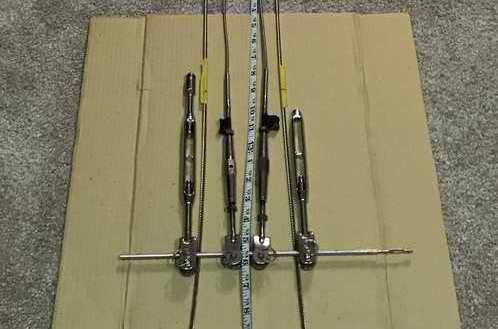 |
Fig 6, MEASURE THE LENGTHS - The Sharpie
points to where the wire is to be cut (dot on tape).
- The final cut length
was confirmed with the shrouds
hanging from the mast as I have never known a hack saw to add wire!
|
|
TOP
|
|
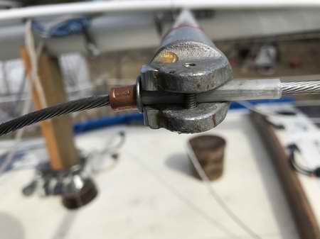
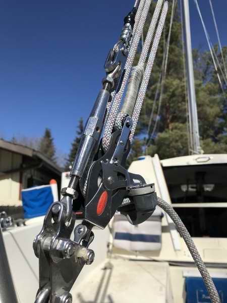
MODIFY SPREADER ENDS, (Spring 2021). Fig 7, NICOPRESS
STOP SLEEVES FOR SPREADERS - The early version spreaders are set at right angles to the mast (horizontal) that can result in a slight downward force at
the tip once the rigging is stressed. This is not a big deal for this robust
spreader but to offset the downward force a Nicopress stop sleeve of soft
copper is crimped to the shroud where it rests snug under the
spreader to support it. The stop sleeve can also offset the downward pull of
a lazy jack
or a flag
halyard. You have to do some vector addition to understand this.
If you are going to stand on the spreaders keep your feet right next to the mast,
otherwise you will be in for a nasty surprise as you smack your butt on
the deck!
|
|
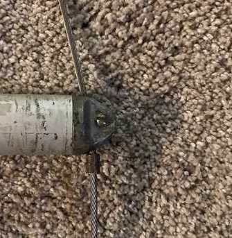 |
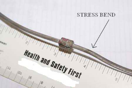
The factory configuration shown at left created the bend below.
Not that bad though.
|
When I removed the vinyl spreader caps I discovered the wire was deformed with an odd permanent bend. This was due to the copper stop sleeve being pushed at an angle, bending the wire with
it. I didn't want this affecting the new wire so to keep it straight
I
flattened the bottom of the spreader tip with a couple of aluminum
wedges epoxied to the spreader tip. Keep reading.
|
|
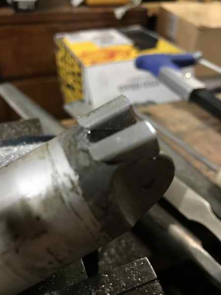
The bottom side of the spreader tip notched with a file to prevent the
wedges (right photo) from sliding outward under load. A precise machine fit.
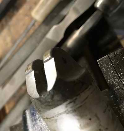
At right are the additional wedges dry fitted prior to grinding. After the epoxy
cured the excess metal was ground flat with a hand file and a Dremel to match the contour of the
spreader tube.
|
|
The SS washer spreads the load
uniformly between the stop sleeve and the wedges. A high density
vinyl tube over the wire insulates it electrically from the spreader. For an exact fit
on Panache the
position of the stop sleeve was marked with the mast standing and
crimped after the mast was lowered. The whole
assembly fits very nicely inside each
vinyl spreader cap. The screw through the spreader tip retains the top shroud on the spreader.
|
|
Dry fit of final assembly below, crimped at right and sealed below right.
|
|
HINT - "You could use your old shroud as a guide to position and crimp the Nicopress stop sleeve ~12' 3 5/8" from the top. But the spreaders require precise placement for equal support. Don't assume the length of the old shroud is correct. Verify by measuring. Because the wire was new I chose to tension the rigging for a week before I compressed the stop sleeves. Each spreader was nudged up just a bit to crimp the sleeve on the shroud, leaving them pointing upwards ever so slightly. Crimp the stop sleeve only once.
- This copper stop sleeve must be slipped over the shroud before the bottom StaLok terminal is fitted. While a round Nicopress sleeve is inexpensive, you can't afford to experiment with this one because you will have to replace the bottom terminal to slip a new sleeve on. Aarch.
|
|
TOP
|
|
INSTALL THE 5/32" SHROUDS, (Spring 2021). |
Prior to stepping Panache's mast I modified the spreader ends with a softer turn to ease the strain on the wire. See Modified Spreader Ends above.
|
|
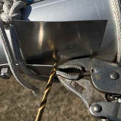
Fig 8, ATTACH ALL SHROUDS TO MAST
-
With the mast down I drilled out the mast tang
holes from 1/4" to 5/32" to fit the Sta-Lok fork pins.
- Best to step drill the tangs using a tungsten
drill bit with a SS sheet behind it to protect the mast and a
vice grip to steady both.
-
Then I attached each shroud to its mast tang with
the pin pointed out so it can't wear on the mast.
- It took a bit of finagling to fit a StaLok pin through
the tang hole but
it popped through when I nudged the tang out. The
lower shroud turnbuckles were attached to the inner holes on the chain
plate and the upper shrouds were left loose.
-
I fit the spreaders to the mast and slipped the upper shrouds through the spreaders ends.
Enlarging a tang hole to 5/32" for a 5/32" pin using a sheet of SS to protect the mast.
|
Fig 9, STEP THE MAST
-
Each lower shroud was secured to its chain plate using a thickening tube over the pin to fit the larger hole in the chain plate. The mast was stepped with the upper shrouds hanging loose
from the spreaders.
- The temporary shrouds used for stepping the mast kept it
centered and the lower shrouds provided the lateral support once standing.
-
Adjust the lower shroud turnbuckles to set
the mast perpendicular (left-right) to the hull.
- Confirmed by using the main halyard touched to each toe rail.
-
Tightened the lower turnbuckles really tight to
remove construction stretch.
NOTE -
There is enough space on a tang to fit
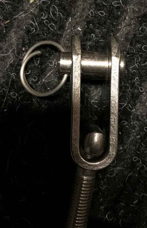
a Sta-Lok fork without touching mast. This photo is prior to locking the cotter pin.
|
Fig 10, CUT UPPER SHROUDS TO LENGTH
-
With each upper turnbuckle screwed in 1/3 I
confirmed the shroud cut marks were correct. (previously marked on yellow tape in Fig 6).
-
The wire was taped to keep the strands bundled for cutting. I slipped a
SS washer and a
copper sleeve
over each upper shroud for the spreader ends. Later I slipped a high density
vinyl tube over the wire to minimize point loading and to insulate
the shrouds from the aluminum spreaders.
- The remaining wire I had left was
just long enough for a future backstay. For now I will use the 1/8"
factory backstay that was modified in Tech Tip F09 for the backstay tensioner.
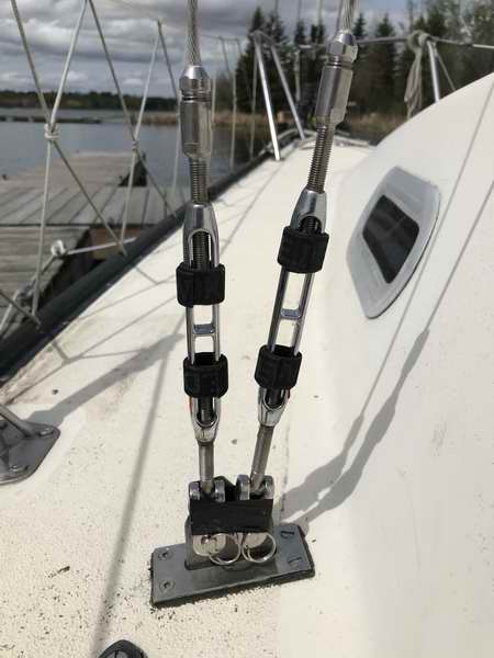
Port turnbuckles tensioned and secured with Blue Wave smart pins.
|
Fig 11, INSTALL THE UPPER SHROUD STA-LOK TERMINALS
-
Installed a Sta-Lok stud to the bottom of each upper shroud. Then screwed a turnbuckle to each and attached it to its respective chain plate with a spacer tube over the pin. Tensioned the rigging really
tight.
-
A week later I marked each shroud where the spreader is to rest on its
sleeve; ~12' 3.75" from the top.
- I stood on a ladder resting against the
back of the mast
to apply tape to each shroud, just under the spreader.
-
Lowered mast, crimped stopper sleeves,
slipped in vinyl sleeves, attached spreader caps. Did a thorough inspection of all rigging
parts to confirm Panache is ready for
another rounding of the "Horn".
-
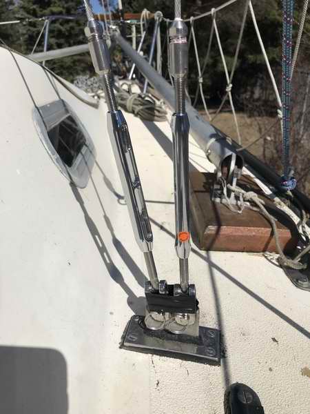
Starboard turnbuckles ready for Blue Wave smart pins.
|
|
Fig 12, JOB DONE. (A dram of Scotch never tasted this good!)
In the final assessment, the upper and lower shrouds were cut to factory length and fit like a glove with turnbuckles screwed in 1/3. In the photo below I've tightened the turnbuckles really hard to remove as much construction stretch as possible during the 3 weeks the mast stood till launch day. The next day a cold front blew through that shook the rigging quite a bit and covered the deck with snow. That shaking helped to remove a lot of construction stretch and couldn't have happened at a more opportune time. Nothing like an initiation from Mother Nature to test new hardware. It will take a few days (~15 hrs) of sailing to remove the last of the
stretch though.
PS: Since I now use the trailer winch to step the mast I no longer extend the mast support post as shown below.
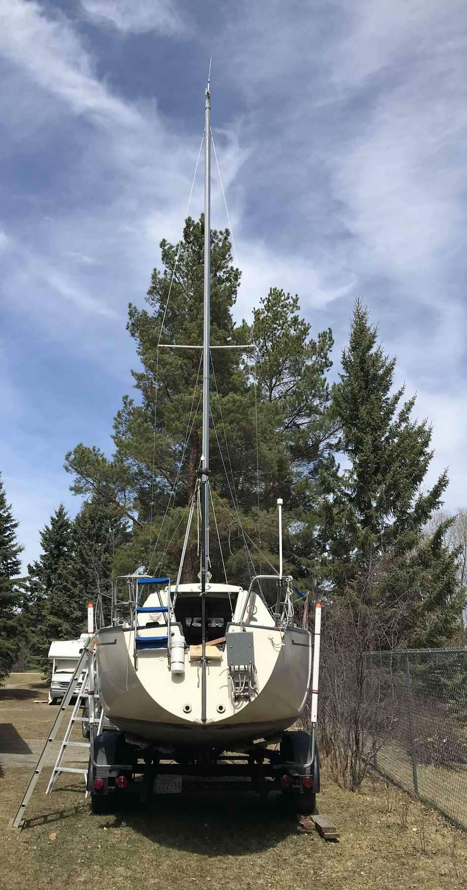
At this point in time all the rigging, except the backstay, is secured with a Sta-Lok terminal on 5/32" SS wire, I crimped the stopper sleeves under the spreaders, installed the spreader ends, locked the cotter pins at each mast tang, and greased the turnbuckles. Only the top of the backstay has a swaged terminal (factory original) and the open end of that terminal points down so I'm not concerned about it for now. I have enough 5/32" wire left to make a new backstay. Its a thing of beauty when a project comes together after so long. Time to go sailing. |
|
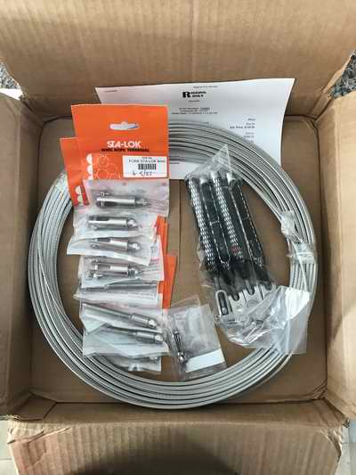
PARTS LIST for 5/32" SHROUDS. |
The box of goodies I received from RIGGING ONLY.
These people really know their stuff and give excellent service.
 |
| 4 ea - Hayn LH Jaw & Body Turnbuckle, 5/16" thread, 5/16" pin, forged T-Toggle, (shrouds). |
SKU: 516FBJ |
| 4 ea - Sta-Lok Stud, 5/32"
or 4mm wire
X5/16" UNF right hand thread, (bottom terminal). |
SKU: 136-04 |
|
4 ea - Sta-Lok Fork, 5/32" wire X1/4" pin, (top terminal). |
SKU: SLFK0508 |
| 2 ea - Sta-Lok Wedge (cone), for 1x19, 5/32"
wire (spares). |
SKU: 138-04-1 |
| 1 pkg of 5
- Sta-Lok Former, 5/32" wire (spares). |
SKU: SLFO05-PK5 |
| 58' - 5/32" 1x19 wire, type 316 SS. (2 upper shrouds) |
SKU: 5321x19316 |
| 27' - 5/32" 1x19 wire, type 316 SS. (2 lower shrouds) |
SKU: 5321x19316 |
| Blue Wave smart
pins for open turnbuckle, 5/16". (Binnacle.com) |
16077 |
TOTAL |
~$725.00 US (2021) |
| |
Replacement Cost? Considering that the Sta-Lok terminals are reusable, I would only have to buy 100' of wire & 12 Sta-Lok formers and wedges (cones) to replace this rigging. This is a minor expense.
|
~$110.00 (2021 cost) |
TOP
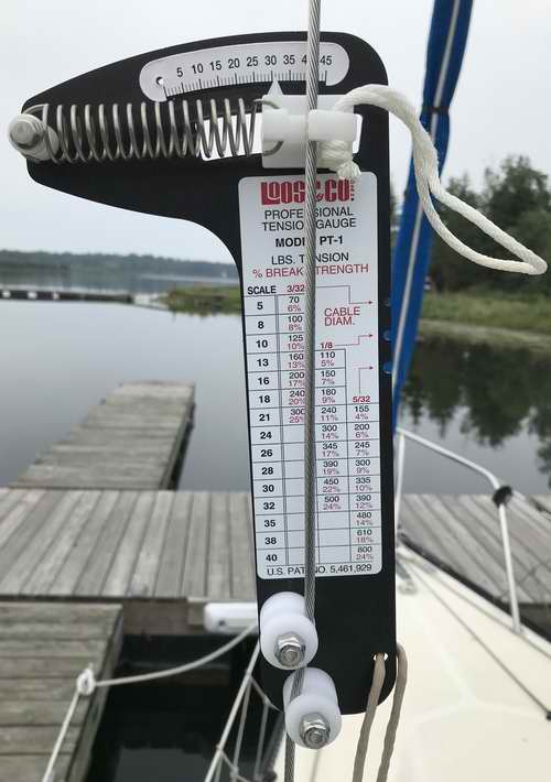
SET THE RIGGING TENSION ON THE WATER, (Summer 2021). |
| After setting the mast straight and adjusting the rigging tension we motored the length of the lake over flat water to Panache's slip. The rig adjustments were "tweaked" in the slip later that day using the Loos PT-1 tension gauge at right. During my first sail I cruised around at near hull speed for the afternoon, heeled at 200 for as much as possible. I was impressed with the lack of stretch the new 5/32"
wire has. Maybe its "waxed car" syndrome but Panache sure felt
solid. By the end of the afternoon the leeward shrouds showed a bit of slack that was taken up with one turn of the turnbuckles. By mid season I've tightened the rigging twice, 1/2 turn each time. In both cases the leeward shrouds were just loose at 200 heel. I'll continue to monitor the rigging but I doubt there will be anymore adjustments. In early August I confirmed the rig tension with a Loos gauge again and I was pleasantly surprised with how equal my field adjustments were compared to measured tension. At this time I released one lower shroud 1/2 turn to remove a bow in the mast which equalized all the measured shroud tensions. As it turns out the gauge showed wire strain at ~11% loading on all shrouds (noted by the pointer at 31) which demonstrates that adjusting the rig tension as per Clark's instructions works. The rigging has stopped stretching as the tension has held steady for the remainder of the summer. At the end of the season Panache experienced a near knockdown with no change in rigging tension. Good stuff.
|
 |
|
|
REPLACE FACTORY BACKSTAY, (Spring 2024).
upper backstay, lower split wire, boom topping lift. Just after the split wire of Panache's backstay pulled out of its single Nicopress sleeve (holding the block n tackle at the bottom of split wire), it changed my understanding of the forces involved. After assessing the age (1977) of Panache's factory 1/8" backstay, I decided to replace it. 47 years is pretty good but nothing lasts forever. The upper part of the backstay was replaced with 5/32" wire to match the rest of the standing rigging and the lower split wire was replaced with 1/8" wire. It could be that I'm sailing Panache harder since upgrading to 5/32" rigging but that certainly wasn't the case when the split wire pulled out of its sleeve! Regardless, the backstay upgrade was relatively easy to do and I'm not about to loose the mast over a simple upgrade. See Tech Tip F09 for caution note that initiated this replacement and
backstay tensioner details.
Panache's backstay tension at rest was measured at ~7% of breaking strength (160 lbs) and when tightened at ~15% of breaking strength (320 lbs).
A Loos Professional strain gauge has an accuracy of +5%.
FABRICATE 5/32" BACKSTAY, (Fall 2023). The top wire of the new 5/32" backstay now has a Sta-Lok eye terminal at top and bottom ends. NOTE - This is one of those times when I received misleading information about the SJ23. Panache was still floating when I was told the masthead casting changed over the years and an early version may not accept an eye terminal. Obviously this is not the case as can be seen in Fig 14 below, but it is best to verify this against your own boat.
|
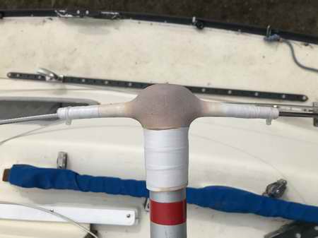
Fig 13, MASTHEAD - The new backstay with Stay-Lok eye terminal will fit in the aft groove with the 5/16" pin securing both the backstay and the boom topping lift bale. The factory backstay was removed in this photo to fabricate a new one to the same length. 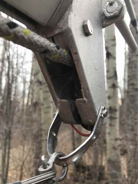
|
Fig 14, MASTHEAD - The masthead showing the backstay Stay-Lok eye terminal and the Dyneema boom topping lift installed on the single pin. The lighter topping lift should interfere less with the telltales and minimize chafe on the mainsail. 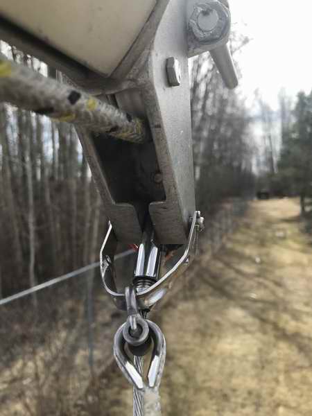
|
Fig 15, STAY-LOK TERMINALS - The 24' coil of 5/32" new backstay wire with Stay-Lok terminals attached. 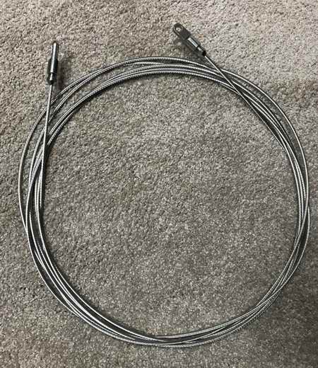
|
Fig 16, WIRE BLOCK - The bottom Stay-Lok eye terminal on the backstay connects directly to the wire block, making a neat connection.
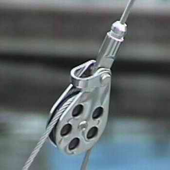
NOTE -
I don't have a use for the shackle at the top of this block but it behoves me to remove it. The second I do, I guarantee you I will need it for something. Murphy strikes again. Aaarch. |
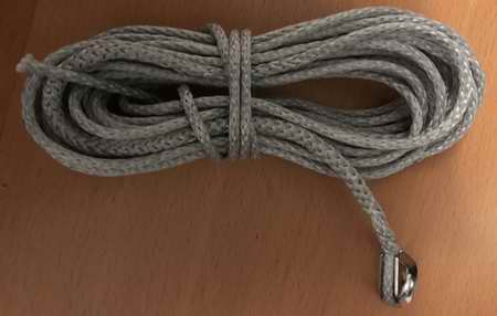
Fig 17, BOOM TOPPING LIFT - The factory 3/32" wire boom topping lift usually droops with a tendency to snag a leech tell tale, threatening to tear it off. So I made a new one from Dyneema.
1/8" Dyneema line is light so it flies off the mainsail to not interfere with the tell tales. It is slippery so a tell-tale releases easily. It is soft so it shouldn't chafe the mainsail leech. The top end was spliced around a SS thimble. The bottom end was spliced in a loop. The whole assembly is strong enough to support the mast should the backstay break (it previously supported the mast when the shroud wire broke) or to lift a person out of the water. I hope I never have to do either of these.
|
Fig 18, BOOM TOPPING LIFT - The 1/8" Dyneema line flying while sailing upwind. It flies like this most of the time. Exactly what I wanted. 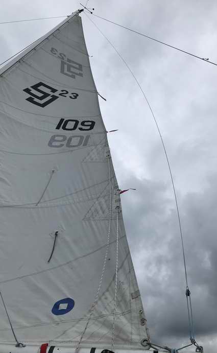
|
FABRICATE 1/8" SPLIT WIRE for BACKSTAY, (Fall 2023). The bottom split wire of the backstay adjuster was fabricated with new 1/8" Imperial gauge wire and Nicopress sleeves. A single oval, zinc plated, copper Nicopress compression sleeve can support 90% of the breaking strength of the 1/8" 7x19 wire, if it is swaged correctly to specification. To exceed 100% strength the split wire was swaged using dual sleeves, spaced ~1/8" apart, with each sleeve swaged 2 times. The protruding wire was at least 2 cable diameters long, prior to swaging. View "How to Select and Crimp a Swage Sleeve" for more details. It was impossible to fabricate a new backstay to the same length as the previous so for this reason the safety wire portion was cut to length after the mast was standing, in Spring 2024.
|
| Fig 18, WIRE BLOCK - The overall ratio of this adjuster is 8:1. When the 4:1 block and tackle tightens all the load is imposed on the wire block. With 50% of the load on either side of the split wire the dual Nicopress sleeves at each thimble must hold this force. This is why all components must fit precise and be swaged to spec. 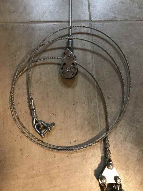
|
Fig 19, NICOPRESS SLEEVES - The new sleeves were swaged ~1/8" apart. There is a SS thimble inside each eye. It rests around a matching size compression tube to eliminate point loading on the bolt.
- Each sleeve should be swaged 3 times but due to the wider width of the jaws in my Nicopress tool they are swaged twice. 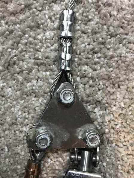
All the prefabrication of the backstay components is complete. Waiting for warm weather to install it. |
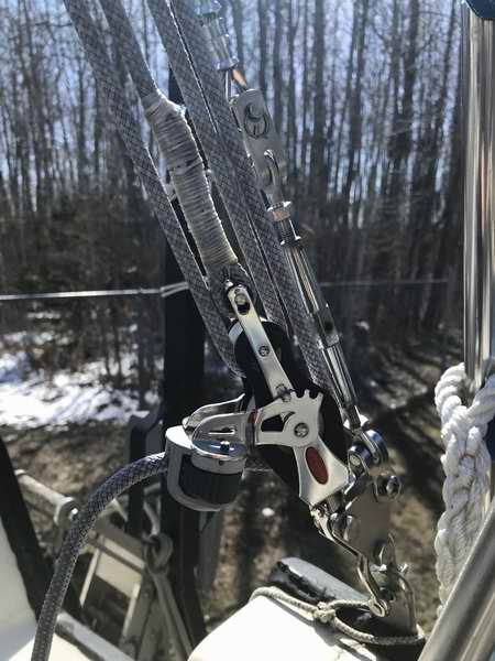
Figs 20-22, FINAL ASSEMBLY - These last three photos reflect the assembly of the adjuster line with the mast stepped in Spring 2024 to confirm an exact fit.
The exposed wire ends were taped over to protect my skin from punctures. Wow are those tiny strands ever sharp. What a nasty way to get an infection. It was a bit hairy to step the mast on my own this time since I didn't have a backstay to stop it from going forward, but I did set the block-n-tackle line fairly close to length before hoisting. Fortunately there was a bit of a head wind to push the mast aft once it stood up. This stability gave me enough time to run to the stern to snub the backstay tensioner line against the forestay. This sounds easy but when you are on your own you can't make a mistake and you have to hustle. It all turned out good. Phew. Out on the water under full rig tension there was a tiny bit of thread exposed on the turnbuckle (barrel style). It was a waiting game to determine if the split wire
would stretch.
It was good at the beginning of the season but half way through I lengthened the turnbuckle and shortened the split wire 1.5" to create adjusting room on the turnbuckle. I need this to tension the forestay correctly and to step the mast. Job done. |
Fig 20, Top tightened slightly during the dry fit.
|
Fig 21, Bottom during the dry fit. 1/4" pin in a 1/4" hole.
|
Fig 22, Bottom during the dry fit.
|
Fig 23, Overall Design from Tech Tip F09. 
This is duck, loon, grebe, goose, pelican and osprey country.
It is absolutely amazing to see pelicans fly in formation into this bay.
|
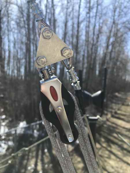
Fig 24, Overall photo of back stay adjuster in final configuration. 
|
PARTS LIST for 5/32" BACKSTAY - RIGGING ONLY. |
| 2 ea - Sta-Lok Eye, 5/32" wire, 5/16" pin, (Top & bottom terminals). |
SKU: SLEY0510 |
| 1 pkg - Sta-Lok Wedge, for 1x19, 5/32"
wire (5 spares). |
SKU: 126-04 |
| 1 pkg - Sta-Lok Formers, 5/32" wire (5 spares). |
SKU: 115-04 |
| 24' - 5/32" 1x19 wire, type 316 SS. (backstay upper wire). |
SKU: 5321x19316 |
| ~15 ' 1/8" 7x19 wire, type 316 SS. (split & safety wire). |
SKU: 5321x19316 |
| 10 copper 1/8" Nicopress sleeves. (for safety & split wire). |
SKU: SLC18 |
TOTAL |
~125.00 $ US (2023) |
TOP
|