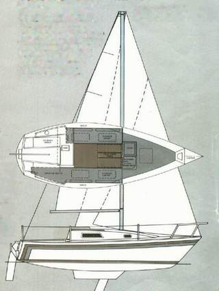
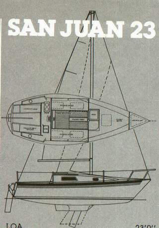
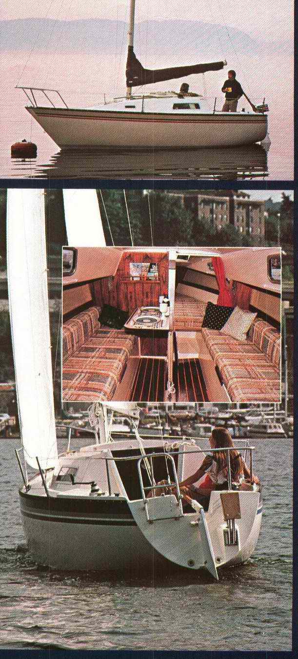
|
SPECIFICATIONS
from the CLARK FACTORY MANUAL.
(with some additional info to make it more useful)
|
|
HULL SPECIFICATIONS |
SJ23 MKI - (shoal draft w center brd),
1975
Designer - B Kirby/D Clark
Builder - Clark Boat Co. (USA) |
SJ23
MKII - (fin keel), 1977
Designer - Bruce Kirby
Builder - Clark Boat Co. (USA) |
| LOA
- Length overall. |
23' / 7.01 m |
23' / 7.01 m |
| LWL
- Length water line. |
20' 4" / 6.2 m |
20' 4" / 6.2 m |
| BEAM
- Hull width at its widest. |
8' / 2.44 m |
8' / 2.44 m |
| WATER DRAFT
- How deep the hull sits in the water. |
(center board up - 1' 11")
(center board down - 4' 9") |
4.3' / 1.31 m |
| DISPLACEMENT
- Total weight of empty hull. |
2700
lbs. / 1,225 kg |
2900
lbs. / 1315 kg |
| BALLAST
-
The early hulls had lead pellets
encapsulated in resin. The last hulls had lead ingots encapsulated
in resin. There might be a small air gap above the ballast. |
960 lbs. / 435 kg |
1100
lbs. / 499 kg |
| HULL
CONSTRUCTION
-
Solid
fibreglass hull below the toe rail. Above the toe rail the deck is wood cored with 1/4" plywood throughout and solid fibreglass in the major structural areas. The
greater curvature of the cabin top and sliding hatch have 3/8" end grain balsa
core. |
|
The MKII has a force grid on the cabin sole to support the heavier fin keel of the SJ7.7. It reduces the cabin height a bit. |
| FREEBOARD
-
Measured at the front of the cockpit. |
~33" / 1 m |
~33" / 1 m |
|
CARRYING CAPACITY -
There is no capacity plate on an SJ23 but you should restrict how much weight is in
the cockpit during rough weather. |
3 adults in the cockpit is not a problem provided 2 sit at the
front with the third at the helm. While it may be tempting for 2
crew to sit at the aft end of the cockpit, the narrow transom cannot
support their weight in anything rougher than "grandmother weather." The extra weight will cause the stern to squat dangerously low. The boat must be
sailed level on its lines to achieve hull speed. |
| AIR DRAFT ON THE WATER -
To float under a bridge, (Allow extra for Windex, antenna or waves). |
~32.5' / 9.91 m |
~34.5' / 10.52 m |
| TRANSPORT CLEARANCE ON A ROAD - To drive under a
bridge. |
~12' / 3.66 m |
~14' / 4.27 m |
|
STANDING
RIGGING -
All measurements with turnbuckles 3/4 open.
(taken from SJ23 MKI manual).
NOTE - While compiling this info, I learned that
early version SJ23 spreaders and mast heads are rigged different from later ones. Who would have thought!
Unfortunately it would clutter up this document to include all
versions, not that I even know them. Shown below is Panache's factory standing rigging from deck to
mast head.
Panache
is the first version SJ23.
|
|
MKI
(shoal draft keel), 1977 |
SJ23 MKI - (shoal draft w center brd),
1975 |
MKII
(fin keel), 1977 |
FORESTAY
TOP - Swaged
eye, e/w 1/4" pin.
Locked with a cotter pin. BOTTOM - Swaged 1/4" stud screwed into
a Ronstan RF354, body & lower jaw turnbuckle. Fastened to chain
plate with a 1/4" T-bolt toggle e/w 1/4" pin. Locked with split
ring.
|
1x19, 1/8" wire,
316 SS.
29'
3-1/4" - top
eye to turnbuckle toggle. |
1x19, 5/32" wire,
316 SS.
~31.47' - top
eye to turnbuckle toggle. |
STEM CHAIN
PLATE
The
Stem chain plate
is (1/4x1)" SS strap bolted to the hull with 7/16" bolts. It protrudes 2" up from the deck
with a 3/8" hole for the forestay.
|
3/8" hole, 1/4"
from top
of chain plate. |
3/8" hole, 1/4"
from top
of chain plate. |
UPPER SHROUDS
TOP -
Swaged fork e/w 3/16" pin
though a 3/16" tang hole.
Locked with cotter pin. BOTTOM - Swaged 1/4" stud
screwed into a Ronstan RF354, body & lower jaw turnbuckle. Fastened
to chain plate with a 1/4" T-bolt toggle e/w 1/4" pin. Locked with
split ring.
|
1x19, 1/8" wire,
316 SS.
25' 10" - top fork to turnbuckle eye.
First version SJ23 - Top of Nicropress sleeve is ~12' 3 3/4" from fork eye
at top. |
1x19, 5/32" wire,
316 SS.
~27' 10" -
top
fork to turnbuckle eye.
|
LOWER SHROUDS
TOP - Swaged fork e/w 3/16" pin
though a 3/16" tang hole.
Locked with cotter pin. BOTTOM - Swaged 1/4" stud
screwed into a Ronstan RF354, body & lower jaw turnbuckle. Fastened
to chain plate with a 1/4" T-bolt toggle e/w 1/4" pin. Locked with
split ring.
|
1x19, 1/8" wire, 316 SS.
13' 5-5/8" - top
fork to turnbuckle eye. |
1x19, 5/32"
wire, 316
SS.
~15' 5-5/8" - top
fork to turnbuckle eye. |
SHROUD CHAIN PLATE
The
Shroud
Chain Plates are (1/4x2x9.5)" SS straps bolted to the
plywood bulkhead with 1/4" bolts. Plates protrude 1 6/8" up from the deck.
|
3/8" hole, 3/8"
from
top of chain plate. |
3/8" hole, 3/8"
from
top of chain plate. |
BACKSTAY
TOP - Swaged eye e/w 1/4" pin. Locked with a cotter pin.
BOTTOM - Swaged 1/4" stud screwed into a Ronstan RF354 body & lower jaw
turnbuckle. Fastened to chain plate with a 1/4" T-bolt toggle e/w
1/4" pin. Locked with split ring.
|
1x19, 1/8" wire,
316 SS.
30'
3" - top
eye to turnbuckle eye. |
1x19, 5/32" wire,
316 SS.
~32' 3" - top
eye to turnbuckle eye. |
BACKSTAY CHAIN PLATE
The
Back Stay
chain plate is (1/4x1)" SS strap bolted to the hull with 1/4" bolts through the transom.
- A hull could have 2 chain plates if a split backstay adjuster is installed.
|
1/4" hole, 1/4"
from top of chain plate. |
1/4" hole, 1/4"
from top of chain plate. |
SPLIT BACKSTAY
(
See Tech
Tip F09)
|
1/4" hole, 1/4"
from top of chain plate. |
1/4" hole, 1/4"
from top of chain plate. |
|
SPAR
(measured)
|
SJ23 MKI - (shoal draft w center brd),
1975 |
MKII
(fin keel), 1977 |
|
Masthead - Cast aluminum pop riveted
or machine screwed to mast. |
- Equipped with two 1/4" OD x 1 7/8" long pins to which
the forestay & backstay swaged eye fittings terminate.
- 4 sheaves (7/16" x 1 3/4" OD) for 3/8" halyard. Turning on 1/4" shaft.
|
- Equipped with two 3/8" OD x 1 7/8" long pins to which
the forestay & backstay swaged eye fittings terminate.
- 4 sheaves (7/16" x 1 3/4" OD) for 3/8" halyard. Turning on 1/4" shaft.
|
|
Mast
- Anodized aluminum. |
26' 7" long aluminum extrusion.
Cross section (3.5 x ~5)" For Class Racing - A 1/2"
wide black band (upper) is to be maintained on the mast, so that the lower edge of the band is to be no higher than 26’
above the mast step. The sail, when hoisted, shall not extend its topmost portion above the lower edge of the band. Another black band
(lower) must be maintained on the mast 24’ from the lower edge of the
upper band to the upper edge of the lower band. The sail shall not be
down hauled down past the upper edge of the lower band.
|
28' 3"aluminum extrusion.
Cross section (3.5 x ~5)" For Class Racing
- A 1/2" wide black band (upper) is to be maintained so that the lower edge is no
higher than 28' above the mast step. The sail, when hoisted,
shall not extend its topmost portion above the lower edge of the
band. Another black band (lower) must be maintained on the
mast 26’ from the lower edge of the upper band to the upper edge of
the lower band. The sail shall not be hauled down past the
upper edge of the lower band.
NOTE - I doubt
there was ever a class created for the MKII. The above
measurements are my SWAG.
|
|
Mast Foot -
Cast aluminum. Pop riveted or machine screwed to mast. |
-
STANDARD FOOT -
5/16" tall (external halyards).
-
OPTIONAL FOOT - ~4" tall (equipped with internal turning blocks
for factory internal halyards).
|
|
Spreaders
- In line, round anodized aluminum. |
1
3/16" OD, 1 1/16" ID and approximately 27" long with a metal or vinyl cap
on the end to lock the shroud to the spreader. For Class Racing
- A spreader shall hold a shroud 26 ¾” from mast (minimum). Cut a
replacement tube 26 1/4" long.
|
|
Boom
- Anodized aluminum. |
The original aluminum extrusion, without
the goose neck or end cap, is about 10' long. However, the length of a boom
may depend on the foot length of your mainsail. Since
there are so many different mainsail designs available these days, some
owners choose to cut off the excess, preferring to clear the cockpit.
Its an easy thing to do. See Tech Tips F20,
F12. For Class Racing -
A black band, 1/2" wide, shall be maintained on the boom, the inner edge
of which shall not be greater than 8’ 9” from the aft edge of the mast.
The sail must not be hauled past the inner edge of the band.
|
| Spinnaker Pole -
Any type of material but usually aluminum. |
For Class
Racing - The spinnaker pole shall not exceed 9’ 6”, measured from end to end. A lanyard is permitted. The spinnaker pole must be used and connected to the mast when the spinnaker is set, and must be used on the side opposite to where the boom is carried.
See Tech Tip F15.
|
| Whisker Pole
- Any type of material but usually aluminum. |
A
(6-12)' adjustable pole is ideal. Best to have a hook at both ends
with a release cable in the middle. For Class
Racing - The whisker pole may be of any length and type.
It is to be used only with a jib and must be attached to the mast on the
side opposite to where the boom is carried.
|
|
Pulpit & Stanchions - Polished Stainless Steel. |
7/8" diameter
tubing. (1" OD). |
|
Toe Rail - Black Anodized aluminum. |
1/2" holes spaced 4"
apart beside the cockpit and 8" apart forward of cockpit.
|
1/2" holes spaced 4"
apart beside the cockpit and 8" apart forward of cockpit.
|
|
SAILS |
SJ23 MKI - (shoal draft w center brd),
1975 |
MKII (fin keel), 1977 |
NOTE - Cloth weight shown below is from the 1980s. Sail cloth today is lighter and stronger than when Clark Sails were made.
Don't be fooled into buying the same weight cloth as shown below. Talk to your sail maker. |
Main
Sail (Clark) - 5.5
oz Dacron.
1 reef. (2 reefs is better).
(Reef when heel exceed 200). |
105 ft2
- luff
24' / foot 8' 9" / leech x'
- sheet ?'. |
unknown |
CLARK JIBS WITH HANKS |
|
A1,
Genoa 153% (Clark) - 3.8 oz Dacron with piston hanks. (up to 12
knots wind). |
201 ft2 - luff 27' 3" / foot 15' / leech 25' 4"
- sheets 29'. |
unknown |
|
A2, Genoa 135% - 4.5 oz
Dacron with piston hanks. (up to 16
knots
wind). |
~161 ft2 - luff
27' 3" / foot ~13' 8" / leech ~23' 8"
- sheets ?'.
(See NOTE below). |
unknown |
|
A3,
Genoa 115% - 5.5
oz Dacron with piston hanks. (10-18
knots
wind). |
121 ft2 - luff
24.8' / foot 10' 8.5" / leech 21' 5"
- sheets ?'. |
unknown |
|
J1, Working
Jib 110% (Clark) - 6 oz Dacron with piston hanks. (12-18
knots
wind). |
95 ft2 - luff
24' 10" / foot 8' 6" / leech 22' 4"
- sheets ?'. |
unknown |
|
J2, Storm
Jib - 10
oz
Dacron, wire luff with piston hanks. (18+
knots
wind). |
40 ft2 - luff 16' / foot 6' 10" / leech 12' 7"
- sheets 31'.
|
unknown |
CLARK JIBS CONVERTED TO FURLING |
| A1, Genoa ~150% (full hoist) - 3.8 oz Dacron with luff tape to fit foil. Flat cut for roller furling.
(up
to 12
knots wind). |
~199 ft2 - luff 27' / foot 14' 10" / leech 25'
- sheets 29'. |
unknown |
|
A2, Genoa ~120% (full hoist) - 5.7 oz
Dacron with luff tape to fit foil. Flat cut for roller furling.
(up to 16 knots
wind). Tech Tip F21. |
~130 ft2 - luff
27' / foot ~11' 3" / leech ~23' 9"
- sheets ?'. |
unknown |
|
J1, Working
Jib 110% (full hoist) - 6 oz Dacron with luff tape to fit foil. Flat cut for roller furling. (12-18
knots
wind). Tech Tip F21. |
~105 ft2 - luff
27' / foot 10' 7" / leech 23' 3") - sheets ?'. |
unknown |
|
J1, Working
Jib 110% (7/8 hoist) - 6 oz Dacron with luff tape to fit foil. Flat cut for roller furling. (12-18
knots
wind). Tech Tip F21. |
95 ft2 - luff 24' 10" / foot 8' 6" / leech 22' 4"
- sheets ?'.
|
unknown |
|
J2, Staysail (Tech Tip F36) - 10
oz
Dacron. Wire luff hoisted on Solent stay. (18+
knots
wind). |
40 ft2 - luff 16' / foot 6' 10" / leech 12' 7"
- sheets 31'. |
unknown |
SPINNAKERS |
| Tri-Radial
Spinnaker
- 3/4 oz Nylon, 75 Stabilkote. |
400
ft2 |
446 ft2 |
| Tri-Radial
Head Spinnaker
- 3/4 oz nylon. |
350
ft2 |
~375
ft2 |
| Cruise Spinnaker
- 3/4
oz nylon. |
380 ft2 |
~400 ft2 |
| North Sails
G-2 Cruise Spinnaker - Big powerful runner. Light to medium wind
speed. |
368.9 ft2 - luff
30' 3" / foot 16' 1" / leech 26' 4" |
unknown |
| North Sails
G-3 Cruise Spinnaker - Flat reacher. Medium to heavier wind
speed. |
313.9 ft2 - luff
29' 11" / foot 13' 11" / leech 25'
9-1/2" |
unknown |
| North Sails
PHRF Max Asymmetric Cruise Spinnaker |
399.5 ft2 - luff
30' 6" / foot 16' 11" / leech 25' 8" |
unknown |
| North Sails
Cruise Spinnaker - G-0 Very flat genoa like a reacher. Light to medium
tight reaching. |
399.5 ft2 - luff
29' / foot 13' 11" / leech 24' 11" |
unknown |
STANDING RIG DIMENSIONS |
| RIG I
- Fore
triangle height (measured from the toe rail height). |
28' / 8.53 m |
30' / 9.14 m |
| RIG J
- Fore
triangle base. |
9.5' / 2.9 m |
9.5' / 2.9 m |
| RIG P
- Mainsail
luff. |
24' / 7.32 m |
26' / 7.92 m |
| RIG E
- Mainsail
foot. |
9.5' / 2.67 m |
9.5' / 2.9 m |
| SA Fore: - Jib. |
1332 ft / 12.362 m |
142.52 ft / 13.242 m |
| SA Main: - Mainsail. |
1052 ft / 9.752 m |
1232 ft / 11.472 m |
| TOTAL SAIL AREA - (100%
fore sail + Main) |
2342
ft / 22.12 m |
2662
ft / 24.712 m |


