| SJ23 Tech Tip F34, (Updated 2022-09-25) Bob Schimmel, Jon Raymond. | |||||||||||||||||||
|
SJ23 Standing Rig Maintenance & Replace Wire.
INDEX - Inspection, Stem
Chain Plate, Backstay Chain Plate, Shroud Chain Plates, Turnbuckles, Clevis
Pin,
Rig Failures,
|
|||||||||||||||||||
|
INSPECTION -
The standing rigging of an SJ23 requires an annual inspection, at the very least. Best to do that after haul out so you have the whole winter to do your repairs. I suspect that most sailors use their rigging till something fails, hopefully close to "terra firma" where it can be serviced. Stainless steel basically doesn't corrode when exposed to fresh water but that doesn't mean you can ignore it. It just happens at a much slower rate. Stainless steel must be exposed to air to retain its protective coating. On salt water stainless steel corrodes faster the further south the boat is. The general consensus is that in the southern US the rigging must be replaced every 10 years and in the northern US it can sometimes be extended to 20 years. Maybe a tad longer in Canada but that depends on the weather. Panache's rigging failed equivalent to the "extended 20 year" time frame. Talk to knowledgeable people in your area to get local advice on this. For
those of you who leave the mast standing year round
a thorough inspection involves a climb to the mast head. While it
is possible to use binoculars to inspect hardware on
a motionless mast, this is not a replacement for a thorough close up inspection
for a microscopic crack that usually requires a magnifying glass. The advantage of leaving
your mast standing is that it is generally protected from physical
damage but then it's also prone to neglect. For those of you who lower
the mast for winter lay up, this is the best time to inspect the rigging. There is a stumblebum risk
of damaging the turnbuckles when the mast is
lying on the deck but judicious placement of your feet can prevent that
problem. |
|||||||||||||||||||
|
STEM CHAIN PLATE
- There is little required to maintain the stem chain plate. Don't let the bow cap leak though.
That being the case the deck plywood under the cap will rot. The bow cap
and its sealant is vital to the health of everything below it.
Monitor these seals like a hungry hawk. See
Tech Tip B25. SPECS - SS, 1" wide,
1/4" thick, protrudes 2" above deck, 3/8" hole, top of hole is 1/4"
from top of flange.
TOP |
|||||||||||||||||||
|
BACKSTAY CHAIN PLATE(S)
- There is little required to maintain a backstay chain plate. Don't let the seal leak where it penetrates the transom.
That being the case, water will flow under the cockpit, fill the scoop
behind the cockpit and eventually fill the port locker when heeled to
that direction. See
Tech Tip F09.
SPECS - SS, 1" wide, 1/4" thick, protrudes 2" above deck, 1/4" hole, top of
hole is 1/4" from top of flange.
TOP |
|||||||||||||||||||
|
SHROUD CHAIN PLATES
- There is little required to maintain the shroud chain plates UNLESS you let the deck seal deteriorate. That being the case, the water will saturate the deck core and the bulkhead below it, resulting in wood rot that is difficult to repair. A myriad of other things in the cabin that can absorb water will likely go mouldy as well. And oh yes, the chain plate can develop crevice corrosion due to lack of air where it stays in contact with a wet bulkhead. Crevice corrosion is where the metal is continually exposed to stagnant, anaerobic water that can be found between a wet bulkhead and the SS chain plate. The deck plate and its sealant is vital to the health of everything above and below it. Monitor these like a hungry hawk. See
Tech Tip B07.
SPECS - SS, 2" wide, 1/4" thick, protrudes 1 7/8" above deck, two 3/8" holes for turnbuckles, top of hole is 1/4" from top of chain plate.
TOP |
|||||||||||||||||||
|
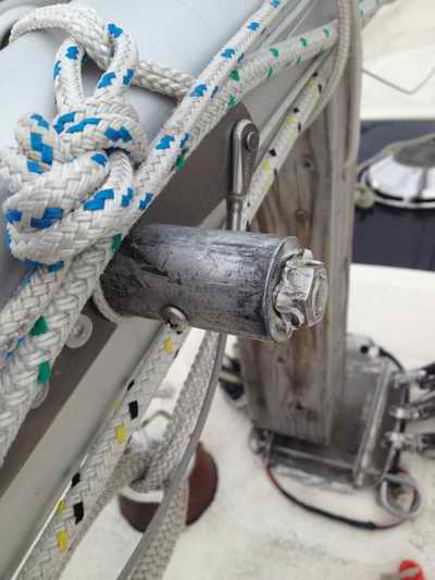
TURNBUCKLES - The
SS turnbuckle thread requires annual lubricating with a water proof
grease (lithium, synthetic or Vaseline) to prevent galling. Also
apply a dab of grease to the barrel openings so the studs can push grease ahead
to lubricate the barrel thread. If left dry the barrel and stud thread
will fuse together (gall), especially under load. The same applies to an open turnbuckle. Galled turnbuckles are a
particular
issue with a mast that stays up year after year. The issue on a
trailerable boat is the tightening and loosening of a dry turnbuckle when the mast is stepped, tearing metal from the barrel thread each time. The
solution for both types of turnbuckles is to grease the studs to full length so the 2
lock nuts and barrel are free to spin as you turn them back 3/8" to step
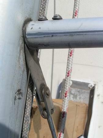
the mast. INSPECT - If a T-bolt toggle is bent, examine it closely for micro cracks using a magnifying glass. The stress cracks created while straightening a bent toggle should make it obvious that it MUST be replaced. Resist the temptation to straighten it unless you want to know where those micro cracks are! Chandlers sell just the toggle (bottom portion of a turnbuckle), making it an affordable repair compared to loosing the mast. I guess they realize some sailors mess up occasionally! See Tech Tip F18 for mast stepping info. TIGHTEN - Always twist the barrel with the correct size wrench around the middle of the barrel while using another wrench on the flat part of the shroud to prevent rotating the wire. Never tighten with a screw driver or such through the hole. This can deform the barrel when it gets really tight. The same holds true for an open turnbuckle. Twist it with a wrench around the middle portion. ISSUE 1 - The diameter of the clevis pin must match the diameter of the chain plate hole for full rated strength. This is NOT the case on the SJ23 where the factory chose to use a 1/4" pin through a 3/8" chain plate hole. This mismatch creates point loading on the pin which greatly reduces the effective strength of the pin. You can restore the strength with a snug fitting SS sleeve slipped over the pin to create a machine fit in the chain plate hole. Ultimately a pin that matches the hole size is simpler and strongest. ISSUE 2 -
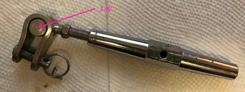
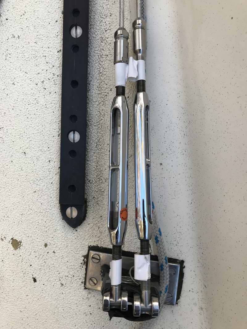
While the upper and lower shrouds have the same 1/4" factory turnbuckles, the toggles are slightly different. The
turnbuckle for the upper shroud has a 3/8" T-bolt with thicker metal in the toggle for the stronger forces of keeping the mast standing. The turnbuckle for the lower shroud has a 1/4" T-bolt
and thinner metal in the toggle for keeping the mast in column.
Verify yours to confirm they are in the correct position. This
is a subtle thing that is easily overlooked and not mentioned in the manual. While you are at it,
position the pin with the locking ring pointing aft so you can see the
ring from the
cockpit. Check them each time you get onboard.
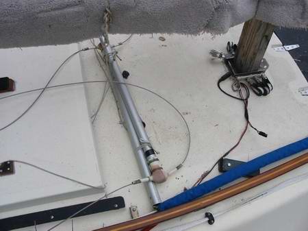
ISSUE 3 - When the mast is down the upper shroud turnbuckles cannot lay flat on the deck and you risk bending or breaking a T-bolt if you step on one. Its a tricky place to walk, so be careful. To minimize this problem, secure the shrouds to the grab rails so the turnbuckles are suspended in the air. As such they are still a tripping hazard but at least you can see them better and reduce the chance of breakage. This is due to the limited 1600 pivot angle of the upper turnbuckle T-bolt.
You could alleviate this by filing the inside corners of the toggle to
increase the pivot angle to 2000. You only have to remove
a little bit of metal from both sharp corners to protect the T-bolt. See
Deck Storage. TOP |
|||||||||||||||||||
|
CLEVIS PIN SECURED WITH COTTER PIN or SPLIT RING - The design of a
clevis pin
is simple but the engineering is far from it. Bolts seldom have
the correct length of clear shank to support a shear load. The clevis pin solves this
problem being entirely clear. The clevis pin that holds a turnbuckle to the deck has to
stand up to an incredible shear force to support the mast under sailing
loads. The fact that so few
pins fail attests to the good design. To install the pin you simply
hold the turnbuckle fork over the chain plate, align
the 3 holes and push the
pin through. The pin MUST fit snug through each of the three holes.
(Its the exact fit in the holes that loads the
entire pin equally to withstand the force). Finally an
exact
size cotter pin or split ring is slipped through the tiny hole across the end of the pin. FULL TIME FLOATING - If the boat stays in the water permanently, it is OK to use a cotter pin. Few people bend a cotter pin properly as many spread the ends only 900 creating the perfect hooks to snag things. To bend it properly, the ends should be turned back all the way to themselves, creating a circle on each side. If properly installed they don't fail and cannot snag things. Owing to this small radius bend, they can crack due to metal fatigue if straightened. For this reason use it only once. A SS cotter pin is slow to install, requiring tools, sometimes has a nasty habit of snagging things and it is difficult to find the correct diameter today. PART TIME FLOATING
- If the boat is ramp launched a split ring is the preferred choice
where you may be pressed to work quickly.
The split ring is quick to install, requires no tools
and doesn't snag things. Rings are generally more available today than
SS cotter pins. While a ring is quick to install, (you knew this was
coming) they too have their weakness. Rings are manufactured
in various diameters and wire gauge (thickness) to match size or load.
If
you install a thin wire ring
A
friend was sailing his SJ28 downwind in heavy air when he
noticed the boom lowering ever so gently into the cockpit.
Thinking that the mainsail halyard had let go he walked to the front of
the cockpit to pull it in. He didn't know it but the clevis pin on
the forestay had let go while he was sailing downwind. In reality
the mast was loose and it was only the wind pressure pushing the sails
forward that kept it standing. Despite all efforts the mast fell.
In the post analysis of the trouble we are pretty sure the clevis pin
slipped (downhill) till the LIGHT gauge split ring was against the
turnbuckle clevis. When the pull from the mast was great enough,
the strain on the clevis pin became unbalanced ever so slightly, forcing
the loose clevis pin to slip down hill with a split ring in tow.
The light gauge elongated ring didn't offer enough resistance to prevent
the pin from slipping through the turnbuckle. A clevis pin
diameter that is not matched to the
hole in the chain plate can cause the hole to deform or bend/crack the
pin. The diameter of the pin MUST match the diameter of the hole or there will
be concentration of stress where the side of the pin touches the hole. A
pin that is smaller than the hole will eventually tilt and strain the
split ring.
* NOTE -
To test the sliding pin theory described above I
installed Panache's forestay pin pointed uphill after stepping the mast. It took only 15 minutes for the pin to slide down while at the dock. The only movement the boat experienced was vibration from the wind. Notice how the pin is stopped by the split ring. Needless to say I reversed the pin (pointed downhill) after this test.
Click here for
images of clevis pins.
TOP |
|||||||||||||||||||
|
VARIOUS RIG FAILURES to WATCH FOR
2 - SWAGE MICRO CRACK - The rest of the swage terminal should be inspected for micro cracks using a magnifying lens. An example of advanced crevice corrosion is shown at right. 1x19 WIRE NICKS & SCRATCHES - Nicks and scratches that cross multiple strands or one strand deeply are also a possible concern and a candidate for replacement. So are flat spots.
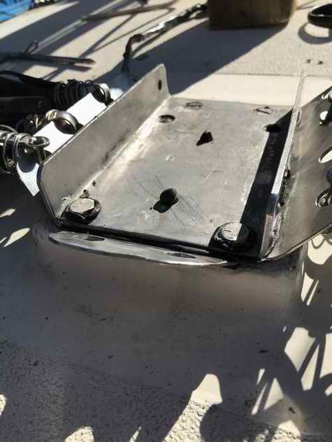
A local SJ24 suffered a broken mast in 2020 which prompted several of us to speculate the reason for the failure. I was shocked to also discover a broken strand (lower shroud) on Panache as I inspected the rigging only 3 months previous. This broken strand is not a show stopper for the remainder of this season but out of an abundance of caution I taped over the break to keep the remaining strands in place. Then I reinforced the shroud with 1/8" Dyneema looped through the top and bottom toggles then tensioned with a trucker's rolling hitch to close the loop. The Dyneema was also loosely wrapped around the shroud to eliminate vibration. The Dyneema could actually slacken the shroud. Needless to say, Panache's shrouds were replaced in the Spring of 2021. By the way, the SJ24 mast broke when a 1/4" turnbuckle toggle on a lower shroud broke while sailing close hauled. When the lower shroud let go, the mast immediately buckled, breaking at the spreaders. This mast has the optional racing foot equipped
turning blocks for
internal halyards and a hinge for stepping the mast. The deck
hinge plate was strong enough to stay attached but tore the
mast foot and some aluminum off the bottom of the mast. While the failure was due to crevice corrosion as shown
in fig 2 above (rigging was 43 years old), stress fatigue while stepping the mast (Got
to loosen the rigging of a SJ23 when stepping the mast) or stepping on
the turnbuckle while it lays on the deck are also suspect. Expect similar breakage on an SJ23, so look after
your rigging. A replacement mast is difficult to find and expensive
to transport.
WIRE KINK & STRESS FATIGUE - A sharp kink in the wire also deserves attention and possible replacement. While stainless steel is malleable, seldom can you straighten 1x19 wire from a sharp kink. But I have straightened a 6" radius bend with no problem but it is your call concerning the condition of the wire on your boat. If you think it looks bad, chances are it probably is and you should replace it. When a kinked or bent wire is repeatedly stretched and released with each tack it will eventually break. Generally one strand first, after which the rest let go, domino style. This phenomenon is called stress fatigue and is exactly the same as flexing a thin steel plate back and forth to break it. This is precisely why the mast tangs must be inline with the wire. When you sail the boat with loose rigging over lumpy water, the vibration will hasten this problem. All this fatigue just takes longer on a boat, BUT the final event happens real quick and comes with a much bigger surprise! Kaboom...... TURNBUCKLE WINTER STORAGE ON DECK - Once the mast is down
resist the temptation to lay the shrouds on the deck. If you step
on a turnbuckle that is attached to a chain plate, you risk bending the
T-bolt toggle. The safer technique is to direct the shrouds up to
the cabin grab rails and secure them there. This
leaves the turnbuckles safely suspended in the air with less risk of stepping on them.
Turnbuckle boots are less of a problem since more air flows through them due to bigger air space. But I removed them from Panache at the same time so I can see the lock nuts and rings. If you still want a turnbuckle boot, get a good one that is sealed to the wire at the top so it can shed rain off the turnbuckle. The occasional dousing of rain is good as it cleans the wire.
But beyond that, keeping SS dry is akin to preventing corrosion.
TOP |
|||||||||||||||||||
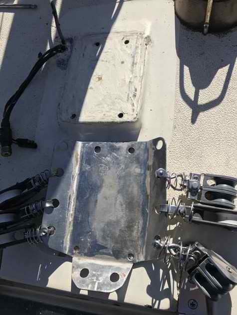
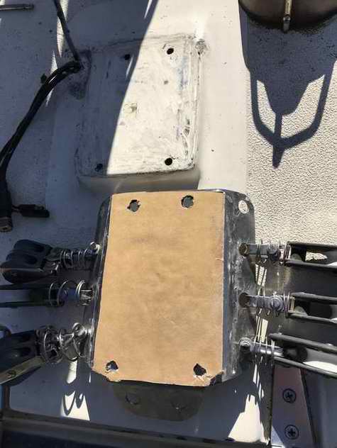
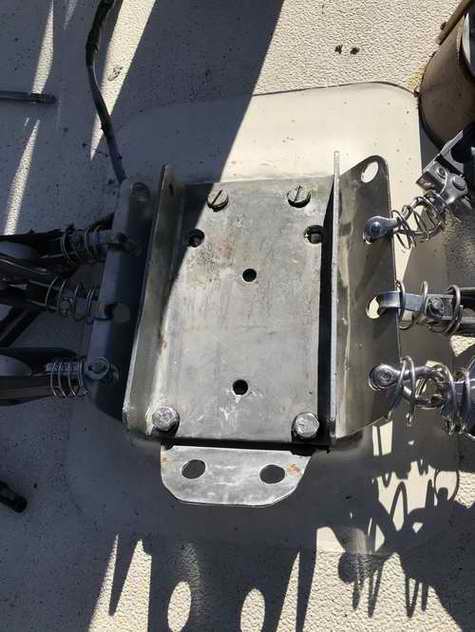
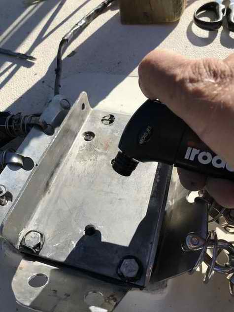
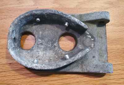 MAST FOOT - The factory mast foot is cast aluminum incorporating an aft hinge that mates with the deck fitting via this custom 1/4" hinge pin to step the mast. The important issue here
is the fasteners that secure the foot to the
mast extrusion, be they pop rivets or screws. The pop rivets on
the foot of Alan's mast at right sheared off when it fell forward due to a broken back
stay. He
considered their release to have saved the deck, which is an interesting
concept. When I installed internal halyards on Panache in 1992 I replaced
the sloppy pop rivets with 1/4" x 5/8" SS NF machine screws for more
strength.
See Tech Tip F03. The screws
were secured with Sikaflex sealant to prevent movement. MAST FOOT - The factory mast foot is cast aluminum incorporating an aft hinge that mates with the deck fitting via this custom 1/4" hinge pin to step the mast. The important issue here
is the fasteners that secure the foot to the
mast extrusion, be they pop rivets or screws. The pop rivets on
the foot of Alan's mast at right sheared off when it fell forward due to a broken back
stay. He
considered their release to have saved the deck, which is an interesting
concept. When I installed internal halyards on Panache in 1992 I replaced
the sloppy pop rivets with 1/4" x 5/8" SS NF machine screws for more
strength.
See Tech Tip F03. The screws
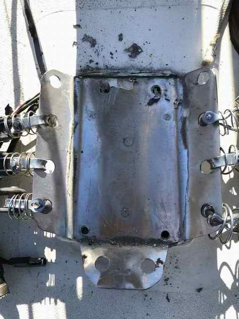
were secured with Sikaflex sealant to prevent movement. Secure fasteners are critical when you step the mast using the tabernacle. If the foot should break free of the mast while it is half way up or down, then you will effectively fire the biggest crossbow you have ever seen! When the mast slides forward, it will do extensive damage to the deck and likely the tow vehicle hitched to the trailer. If you happen to be in its path, you will require surgery! Think about it!
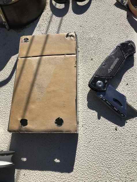
REQUEST FOR ASSISTANCE - This plea for help came from a desperate SJ23 owner in 1983.
Answer - "Your drawing is correct. The mast foot flange goes 7/8" up from the base, inside the mast. Tap NF thread in the base for a bolt on each side, 1/4" forward of the old pop rivet holes OR if the metal is still good enough, use the old pop rivet holes and tap for a 1/4" bolt". Best of Luck, Dave Clark. NOTE - While the existing aluminum pop rivets that secure the base of the mast may be strong when they were new, if they let go while the mast is close to horizontal, the mast will shoot forward like an arrow. This will do considerable damage and injure somebody if they are standing in the way. Therefore, replace the aging pop rivets with 1/4" stainless machine screws tapped into the mast base. Fine thread is stronger than coarse thread. Prevent them from corroding or turning out by applying a thin coat of marine silicon sealant on the thread. TOP
|
|||||||||||||||||||
|
|||||||||||||||||||
 SPREADERS & COMPRESSION BOLT
- The hollow mast of an SJ23 is equipped with a compression bolt between the spreaders to survive the heeling
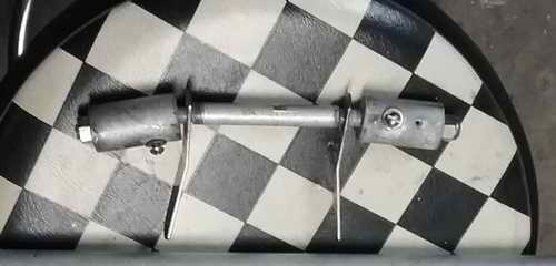
forces beyond 200. As the mast leans with the force of the wind, the windward upper shroud pushes the spreader into the side wall of the mast. This in turn pushes the internal compression tube against the leeward wall. Since the compression tube maintains the space between the mast walls, it retain the form of the mast, keeping the walls in column to prevent a collapse. SPREADERS & COMPRESSION BOLT
- The hollow mast of an SJ23 is equipped with a compression bolt between the spreaders to survive the heeling
forces beyond 200. As the mast leans with the force of the wind, the windward upper shroud pushes the spreader into the side wall of the mast. This in turn pushes the internal compression tube against the leeward wall. Since the compression tube maintains the space between the mast walls, it retain the form of the mast, keeping the walls in column to prevent a collapse. The SJ23 assembly is quite a clever design as it serves multiple functions through simplicity. It consists of a precise length aluminum sleeve through the mast (compression resistance), a 1/2" threaded SS bolt (threaded rod) through the sleeve with bent ends (spreader angle), two SS tangs to attach the shrouds to (tension), two aluminum stubs slipped over the threaded rod ends (to fit the spreaders over) and finally SS nuts and washers to secure it all. "I have never been able to remove the spreader compression bolt from Panache's mast so I'm grateful for Jon Raymond who emailed this photo to me. The left end is bent a bit too much due to an incident he had! The right end shows the correct angle. Jon's bolt assembly is from a later version SJ23 that has slightly upward angled spreaders to bisect the angle at the shroud and mast tangs that pivot on the bolt instead of being riveted to the mast. The spreaders on the first version SJ23's are horizontal and the tangs are pop riveted to the mast." The factory spreaders are made of heavy gauge 1" OD aluminum tubing that slip over the two aluminum stubs. Below you can see the small sheet metal screw that secures the base of the spreader to the top of its stub. The screws on Panache are 1/2" long and bottom out in the stub. They must be removed to release the spreaders after the mast is down. "I set the screws back into each stub for road travel to be ready for next Spring. While I've never lost one I also keep spares in a 35MM film canister."
The compression rod and stubs also secure the lower shroud tangs. Each tang MUST be bent to align with it's shroud. If it is out of alignment, it will eventually break in the same fashion as described above in stranded wire.
Note the different attachment of an early version tang (left) that is pop riveted and glued with sealant to the mast above the stub versus a later tang (right) that is slipped loosely over the compression rod.
For secure road travel I tie the spreaders to each other on deck. Many sailors use a vinyl spreader cap over each end to protect the sail cloth. "Panache's spreader caps are pretty weather beaten as they should be white but the vinyl is in good condition. They will do till they get too brittle."
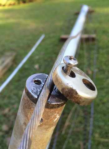
EARLY VERSION SJ23 SPREADERS - At the outboard end of early spreaders is an aluminum casting with a split end to secure the cap shroud. The upper shroud goes through the split and is held captive with a small screw that closes off the split. This is required to keep a leeward shroud attached while sailing or to keep both shrouds attached when stepping the mast. The casting is threaded for the machine screw. The upper shroud has a stopper compression sleeve that rests under the spreader to support it. This style cap should be covered with a vinyl spreader cap to protect the jib. Although you would be hard pressed to sheet an SJ23 jib in that tight. HINT - "When the upper shroud is tensioned against the flat recess of the casting, it makes an abrupt turn over the sharp edge of the cap as it goes to the masthead, resulting in point loading of the wire. To alleviate the point loading, round off the top of the recess with a small round file, leaving the metal smooth with the correct radius to match the wire diameter. There you go, good for a few more miles through the Southern Ocean!"
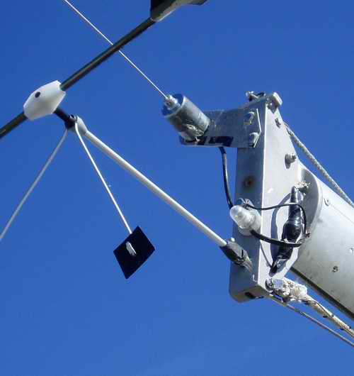
When a spreader bisects the angle to the shroud (highlighted in photo), the compression force on the spreader is balanced (directly along the spreader). It should go without saying that the port and starboard angles of the spreaders must be identical. Unequal support may result in spreader collapse followed by mast failure.
WIRE/ROPE HALYARD WEAR - Early version SJ23s all had wire/rope halyards to eliminate stretch. The masthead sheaves have duel grooves to accept both. Problem is, if the wire portion of the halyards are tied off at the base of the mast the wind will eventually whip them sideways. The wire rubs on the spreaders, resulting in lots of wear over the years. If you had no other reason to replace the meat hook laden halyards, then this would be it. Jon Raymond
|
|||||||||||||||||||
|
About the only thing you have to maintain here are the nylon halyard sheaves. I've inserted brass bushings in Panache's sheaves and oil the bushings annually. These sheaves spin over a 1/4" SS steel bolt. Just inspect them in the Fall for wear and replace if they fit sloppy. You could upgrade them to ball bearing sheaves and be done with this maintenance but that's no fun. Buy a UV resistant sheave so it is not subject to deterioration from the sun. I'm still sailing Panache with the factory sheaves. See Tech Tip F03 for sheave info. The SS pins for the fore and aft stays are equipped with cotter pins outside the masthead. This is absolutely mandatory to ensure they don't fall out and the stick stays standing. Bend the cotter pins back fully around the pin. Also check the rivets for tightness to the mast extrusion. Notice that the VHF coax and a Windex light power cables go through small holes I drilled through the top of the cap. This keeps the cable straight, eliminating stress due to a cable bend below the cap. Silicon sealant is jammed around each cable to insulate and eliminate chafe.
As for this funny looking Windex, someone dared me to make a working unit from broken
parts, claiming it couldn't be done. The mid block is a piece of
UHMW that houses the bearing. The black rod is an aluminum arrow
shaft with the target tip at the front and some very thin sheet aluminum
vanes epoxied to the back. The tricky part was gluing the weights
inside the shaft at the correct balance point. The set screw goes into the slot around the
bottom of the shaft. This minimizes the chances of
loosing the Windex if the screw is loose. Quite often 2 birds will ride on the pointer, one on either end. Its hilarious to see them sliding sideways to balance their weight. So far this "Windex" has worked for 25 years.
TOP |
|||||||||||||||||||
|
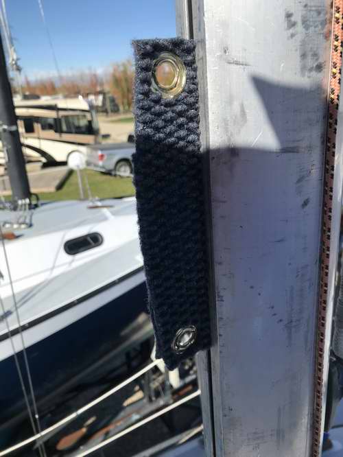
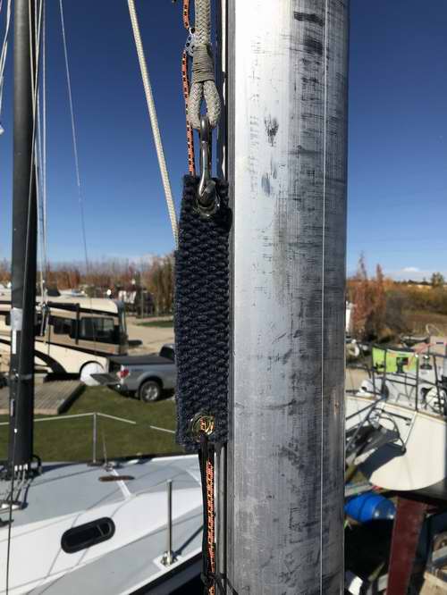
MAST KERF - Want to drop your mainsail in a jiffy? Then clean and lubricate the mast kerf. This "brush" is made from a piece of rug folded over with a couple of brass eyes stamped in the ends. Slide the "brush" into the mast gate and hoist it with the halyard, then pull down with another line. Test the pull down at the bottom before you hoist it out of reach! If you feel a snag investigate it before pulling through it. Spray soap on the "brush" to clean the kerf then spray lube on another onet to lubricate the kerf. Its best to make one for cleaning and one for lubricating. This is a Bayfield 25 mast that belongs to a friend. I made this "brush" for him to fix a problem with a sticky mainsail. Problem solved.
|
|||||||||||||||||||
|
See Tech Tip F34a - 5/32" SS Rigging for Panache. See Tech Tip F34b - Dyneema Rigging for Goodpain. |
|||||||||||||||||||
|
Return to Tech Tip Index. . . . . . . . . . . . . . . Have a Question? |
|||||||||||||||||||
 UPPER SHROUD
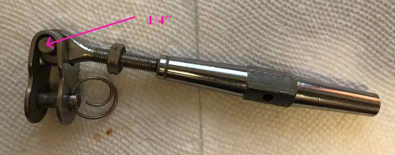 LOWER SHROUD
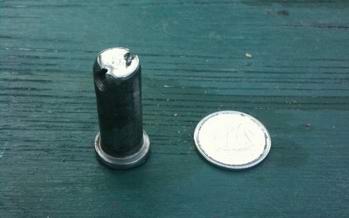 that leaves slop in the hole, it
probably can't stop a pin from sliding out. The ring gets
elongated as the pin slides out. Sometimes
a worn ring turns off with vibration. I don't have the time to watch how this happens but I have seen several rings that were just
about ready to drop on the deck. All of them were light gauge
wire. There are good designs that can't slip off but they are
difficult to find.
that leaves slop in the hole, it
probably can't stop a pin from sliding out. The ring gets
elongated as the pin slides out. Sometimes
a worn ring turns off with vibration. I don't have the time to watch how this happens but I have seen several rings that were just
about ready to drop on the deck. All of them were light gauge
wire. There are good designs that can't slip off but they are
difficult to find.  This
is when an unloaded pin can slide, aided with gravity and vibration.
While the damage to the end of the pin suggests the split ring was
pulled through the turnbuckle hole, the ring might have partially backed
out of the pin hole. We are not sure which it was. It is
very difficult to believe but the evidence suggested it was pulled
through. (The damaged pin is shown next to a dime).
This
is when an unloaded pin can slide, aided with gravity and vibration.
While the damage to the end of the pin suggests the split ring was
pulled through the turnbuckle hole, the ring might have partially backed
out of the pin hole. We are not sure which it was. It is
very difficult to believe but the evidence suggested it was pulled
through. (The damaged pin is shown next to a dime). 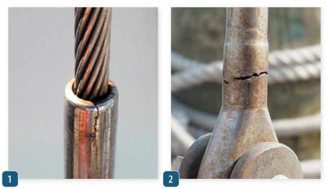 1 - SWAGE CREVICE CORROSION - Of all the terminals fittings found on a sailboat the deck level swage terminal is the most common source of failure. This is due to salt water intrusion and to a lesser degree fresh water intrusion. The water runs down the 1x19 wire and wicks inside the swage. The damage of freeze expansion can take years to set in. An example of the dreaded crevice corrosion is shown at right.
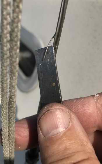
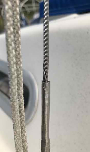 1x19 BROKEN
STRANDS, (2020) - A strand that stands proud, particularly where it enters
a swage terminal, is highly suspect. That was the case shown here on Panache's factory original lower shroud. While
the rigging is 45 years old, the boat was used only 6 months of the year
and stored dry under a tarp for the other 6 months. Panache has
only seen fresh water but this failure is within her expected use rate.
1x19 BROKEN
STRANDS, (2020) - A strand that stands proud, particularly where it enters
a swage terminal, is highly suspect. That was the case shown here on Panache's factory original lower shroud. While
the rigging is 45 years old, the boat was used only 6 months of the year
and stored dry under a tarp for the other 6 months. Panache has
only seen fresh water but this failure is within her expected use rate. 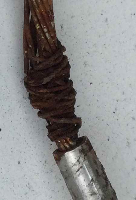 Hutchamia - Notice the multiple broken strands and advanced corrosion in this SJ23 shroud. It is corroded about half way through. I think the previous owner tried to maintain some strength by wrapping the wire with steel strands and then taping over the "repair'" to cover the "meat hooks". Problem is, the tape sealed the SS in a pocket of anaerobic water, thereby blocking any drying air. In time that started the
 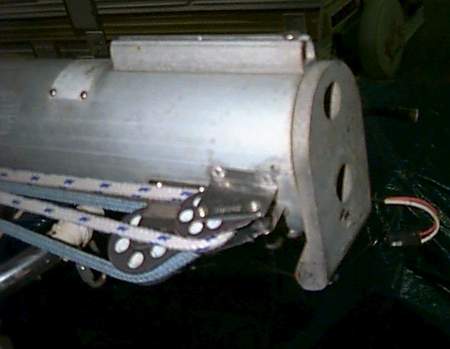 Question
- "We had a very bad experience raising the mast on our SJ23 and
I need a little advice on the repair. Apparently not enough thread
was engaged in the backstay turnbuckle and
when my
wife stepped off the boat the mast started to sway forward just when it let loose. I
managed to steady the mast, rushing up from below, but the tilt sheared
the two aft pop rivets near the pivot pin of the mast base. Now I'm afraid
that the butt casting will disengage when the mast is
lowered.
Question
- "We had a very bad experience raising the mast on our SJ23 and
I need a little advice on the repair. Apparently not enough thread
was engaged in the backstay turnbuckle and
when my
wife stepped off the boat the mast started to sway forward just when it let loose. I
managed to steady the mast, rushing up from below, but the tilt sheared
the two aft pop rivets near the pivot pin of the mast base. Now I'm afraid
that the butt casting will disengage when the mast is
lowered. 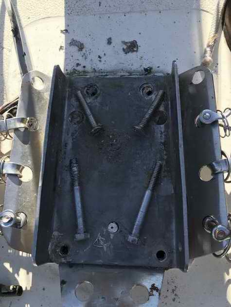
 LATE
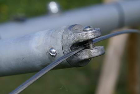
VERSION SJ23 SPREADERS -
At the outboard end
of later version spreaders is an aluminum casting with a cap that fits snug
over the upper shroud. The shroud must be secured under the cap to
keep a slack leeward shroud captive while stepping the mast or when sailing.
LATE
VERSION SJ23 SPREADERS -
At the outboard end
of later version spreaders is an aluminum casting with a cap that fits snug
over the upper shroud. The shroud must be secured under the cap to
keep a slack leeward shroud captive while stepping the mast or when sailing. 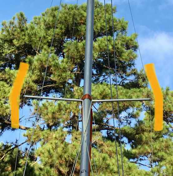 Positioning
the cap along the shroud is a bit of a juggling act. With the mast
horizontal and the shroud tightened, push the spreader up a bit while holding the shroud tight, then
tighten the cap. When the turnbuckles are tightened, the angles
above and below should be equal and the compression
force on the spreader will be directly in line with it.
If they aren't equal, move the cap up or down accordingly. You'll know
it is correct when you can just slip the spreader over the stub.
Positioning
the cap along the shroud is a bit of a juggling act. With the mast
horizontal and the shroud tightened, push the spreader up a bit while holding the shroud tight, then
tighten the cap. When the turnbuckles are tightened, the angles
above and below should be equal and the compression
force on the spreader will be directly in line with it.
If they aren't equal, move the cap up or down accordingly. You'll know
it is correct when you can just slip the spreader over the stub. 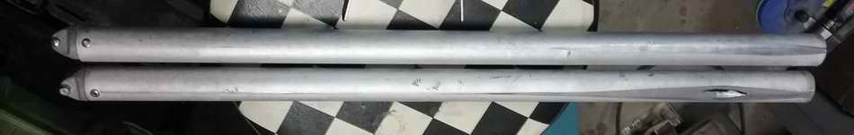