|
SJ23 Project 10, (Updated
2017-12-31) Emunah, hull 544, A Restoration by Randy Cook |
|||||||||||
|
|
|||||||||||
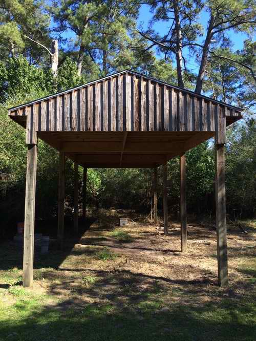
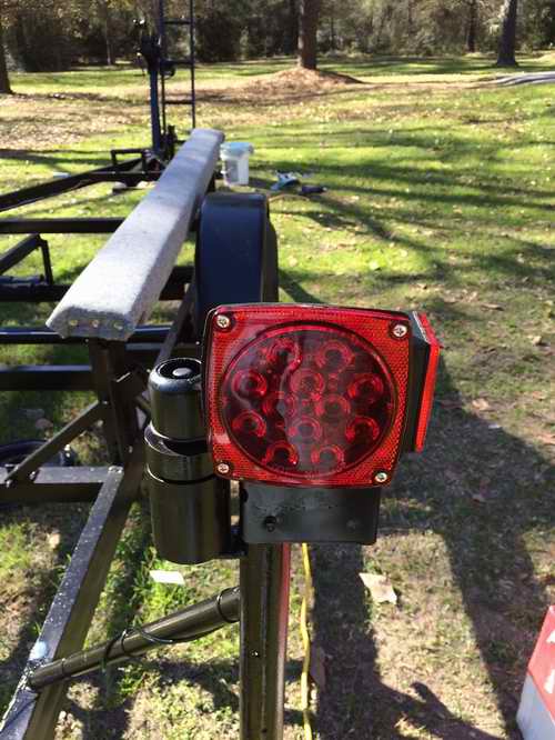
| TRAILER - The trailer had some dire needs so this was tackled
first. After all, from where I live I have to haul the boat down a
freeway every time I use her. So this job was important. The
boat was hoisted off the trailer using two cargo
straps slung from the shed posts. That's only 700 pounds per strap end for an empty hull. Well within limits.
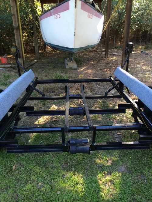
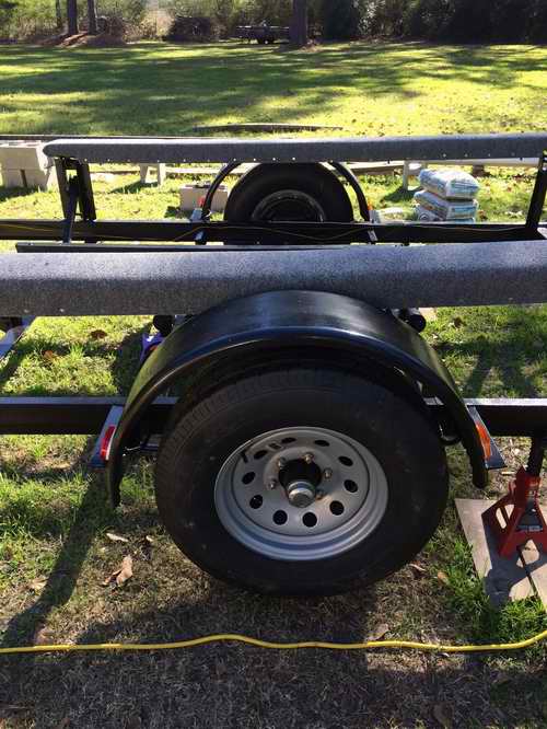
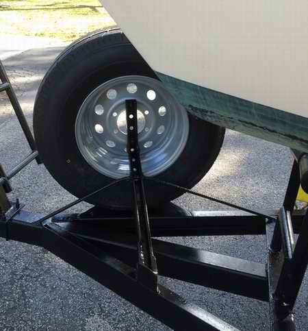
With the trailer free of the boat it was easy to paint the metal, replace the bunk boards, install new rims with tires, add a break away switch and install maintenance free LED lights. The original bunk boards were no longer up to the task and were replaced with stronger ones consisting of two laminated (2x6)"s. They were bent to conform to the hull shape by hanging a weight in the middle, then glued and screwed to each other while in their bent shape. They were left to hang with the weight till the glue fully cured. Then it was time to add the rug, leaving the bottom of the bunk board exposed to ventilate water, thereby preventing wood rot. A last thought was to add some secure tie down straps. These are well documented in Tech Tip A01. The hull was lowered on the trailer and pushed back to the protection of the pole shed for further assessment. While it was there it was easy to fit a roller under the bow and add mounting hardware for the spare tire. TRAILER SPECS - Welded steel frame, single axle rated at 5000 lbs.
The 10 ply tires are rated for 2830 lbs at 80 psi max pressure. |
|||||||||||
HULL -
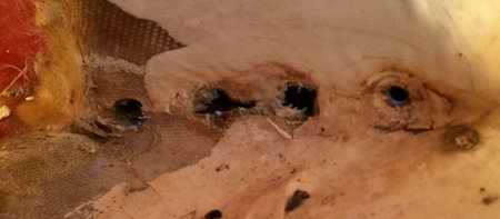
The next job was to tackle the deck holes around
the chain plates. There were some gaping holes around them that exposed the
wood core. The exposed wood made it important to keep
the deck dry under the protection of the pole shed.
But no time to waste because rain and muggy weather will soon be here. It may not look like it but there is sealant under the screw heads. This is a very neat installation. Click here to read about sealing a chain plate.
So while Randy was in the mood to seal the deck, a rain storm was in the weather forecast, he sealed the last of the deck leaks. The stanchions had never been removed since the factory installation. The butyl rubber sealed the deck perfectly.
CABIN - Next the cabin was gutted, fiddles & wall fabric removed and cleaned ready for some interior jobs.
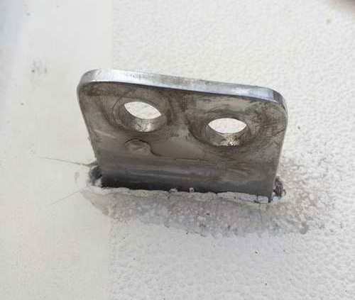
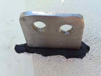
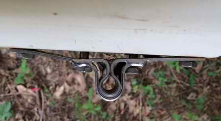
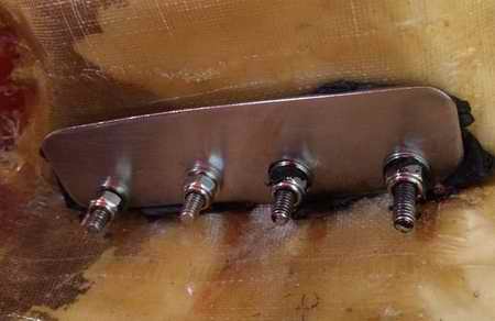
The previous owner used the rudder to "feel" the bottom and bent the lower gudgeon in the process. This tore out fibreglass which naturally caused a leak beside the bolts. So after repairing the damaged fibreglass with epoxy Randy strengthened the installation with a single stainless backing plate behind all four nuts. This guy really believes in making is tough to break! Longer bolts were required for the extra thickness and the holes were sealed with lots of butyl rubber. Much of it oozed out as the bolts were tightened, ensuring a water tight seal.
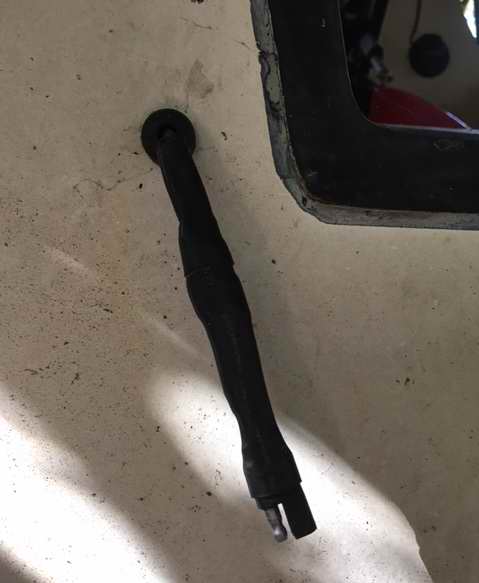
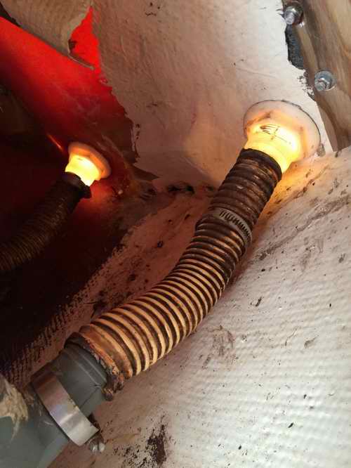
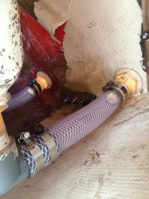
So while he was under the cockpit (probably the least fun place to work) it was time to replace the aging cockpit drain hoses. As you can see the old hoses were not rated for marine use. They were also not fully slipped over the barbed fittings and were secured with only one clamp. Because these hoses are so flimsy they should never have been installed and they should have had two clamps. The new fiber reinforced hoses are installed correctly with the clamp screws on top so they have a fighting chance to stay corrosion free and can be adjusted later in life. Water test -> ....... no, nada, zero, zilch leaks! Tech Tip B17.
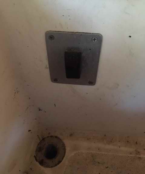
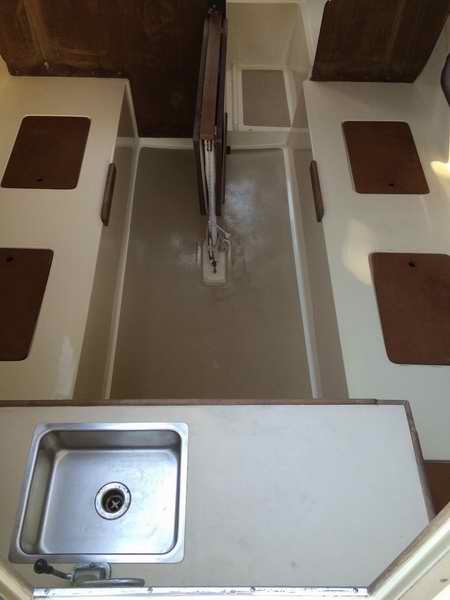
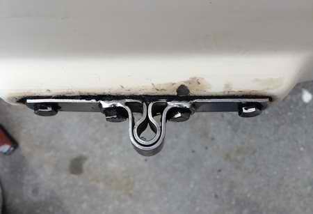
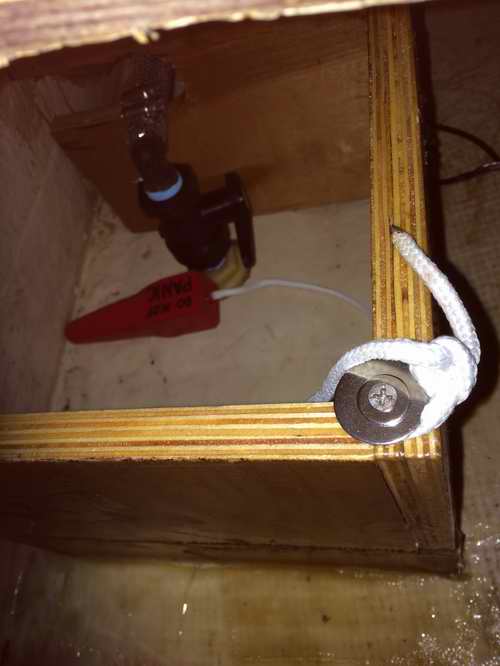
Next on the list were the last two holes that might sink Emunah; the sink drain and the
knotmeter. The speculation is that the old valve handle was broken off
by a deck "ape" so Randy replaced the valve. Not even the guy at West
Marine could understand how the handle broke. So as a precaution
Randy installed a protective cage around the valve to protect it from a sliding object. See the LARGE limber hole at the lowest points for water to flow through and the red plug in case of a leak.
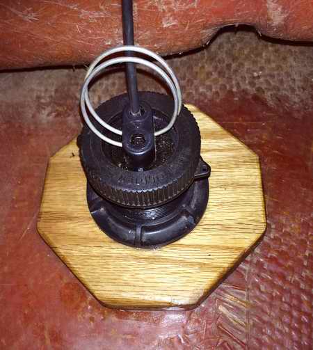
The knotmeter above received a new epoxy saturated backing block to beef it up and was bedded to the hull with butyl rubber.
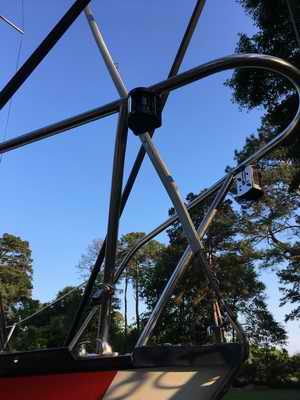
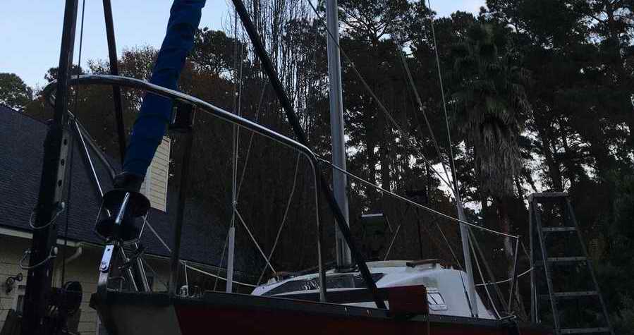
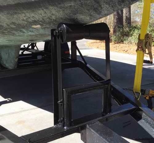
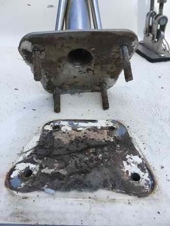
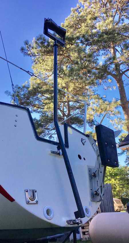
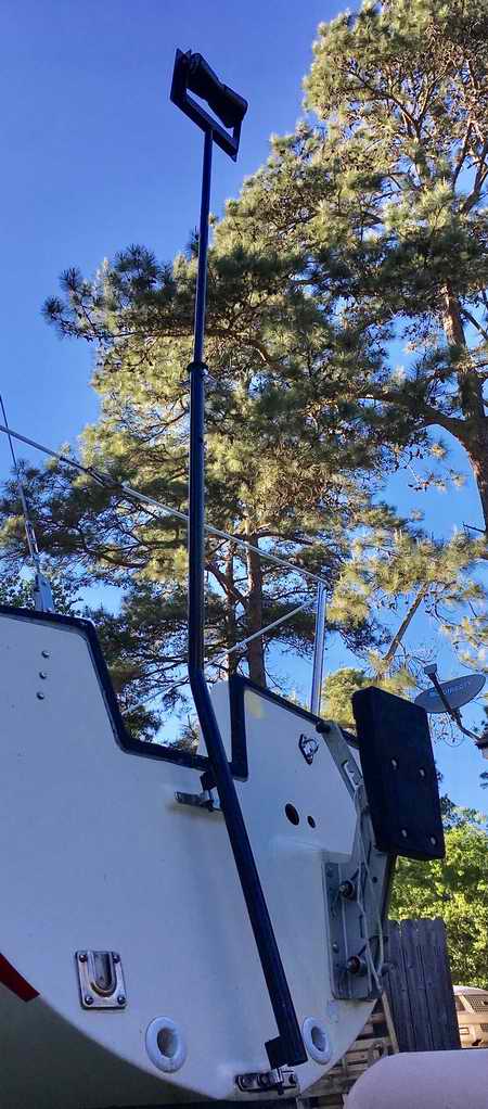
STEP MAST - Below is Randy's version of a transom support post to transport the mast. He went one step further by making it telescopic. Shortened is for road transport and extended is to lift the mast the initial 300 to assist in stepping it. Without this initial lift it is next to impossible to pull the mast up off the deck even with a block and tackle from the bow. Lateral support will be two lines tied from the roller at the top to the cockpit cleats using a cam cleat to allow for extension of the post. This telescopic feature makes it possible for one person to step the mast.
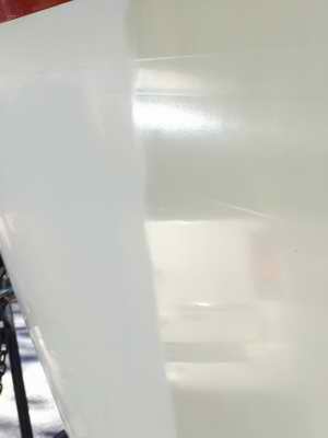
The toe rail was painted with black "Rust-Oleum high performance enamel". A very tough finish that sets in 15 minutes. The cove stripe was repainted with Interlux Brightside paint; brushed and "tipped" with a wedge foam brush. Note that is was extended down the aft of the hull. "Repainting has to be done in multiple thin coats to prevent weeps and sags and done in small sections so it can be tipped before it dries. If you wait too long before tipping, it leaves brush marks." The gel coat was buffed with 1 quart of 3M Marine Restorer and wax. Since it was so badly oxidized Randy chose the most aggressive rubbing compound, applying and polishing it with a buffing pad on an electric drill. "This job must be done in the shade with low humidity. Do small areas at a time" 2.5 hrs per side.
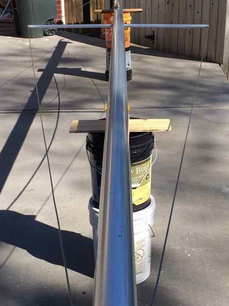
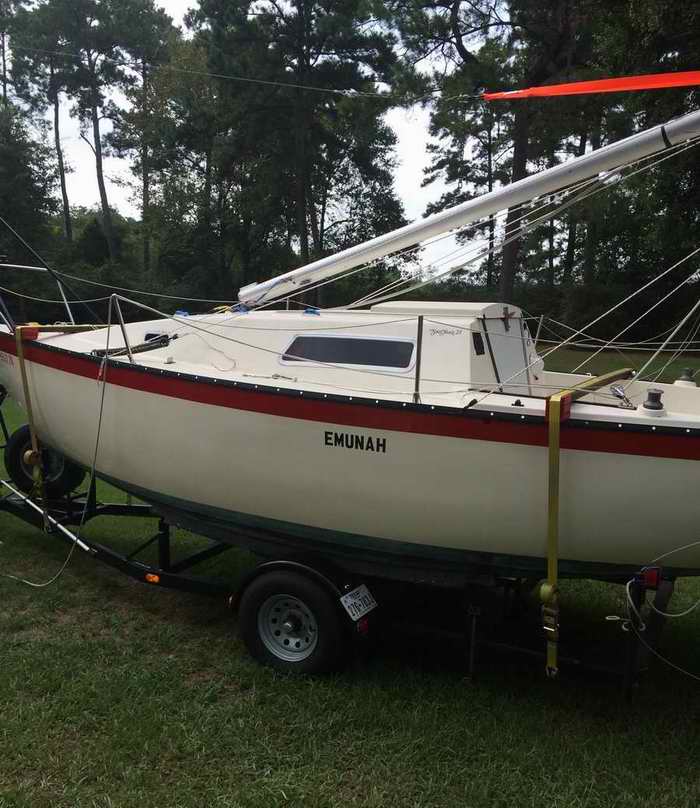
The mast stepping hardware consists of a guyed pole mounted at the front of the trailer. The pole is guyed at the front for stiffness and angle braced to the toe rails to prevent sideways movement. It uses the huge mechanical advantage of the trailer winch to raise/lower the mast via the sheave at the top. Since he must stand at the trailer winch to operate the system he has also incorporated two temporary shrouds equipped with springs to keep the mast centered over the hull. The two lines tied at the cockpit tracks are to pull the mast aft for lowering it. An initial pull is required to overcome the lift motion due to the mast step. It is not evident in this photo but the free ends of the lines are lead forward where Randy can tug on them to pull the mast aft.
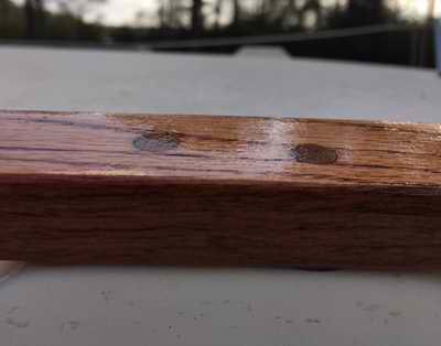
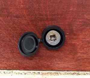
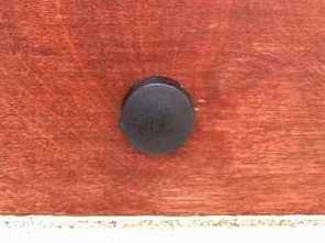
2016-12 - As you can see blow the fasteners were nicely hidden behind wood plugs and the wood coated with Cetol to protect it from the weather.
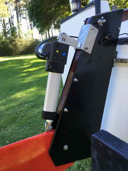
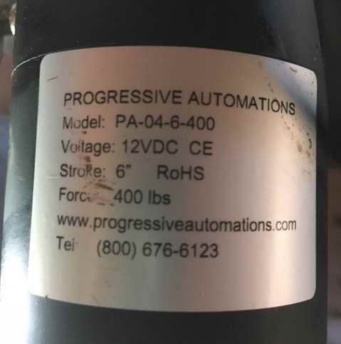
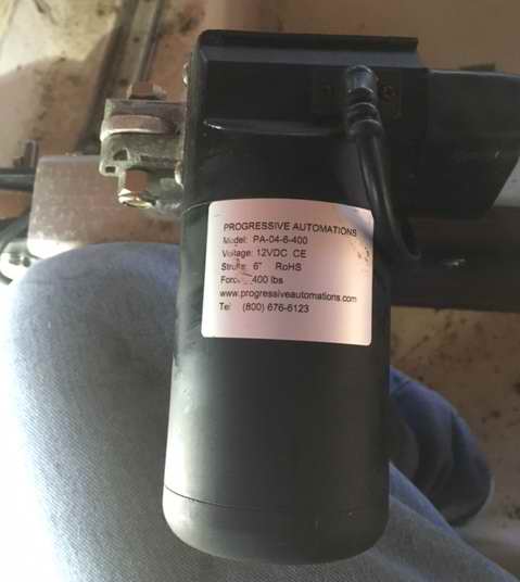
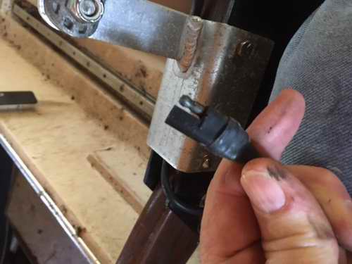
Actuator - Progressive Automations, Mod PA-04-6-400. If the actuator can raise the blade above water, it is certainly strong enough to do so in the water.
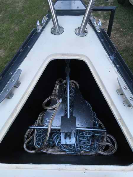
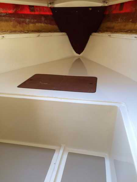
________________________________ Next it was time to tackle the leaking locker lids. This is described in Tech Tip B15. Anchor Locker - The locker holds 200' of 1/2" line with 25' of 5/16" chain and has room to spare. The line is secured to the bulkhead and the lid is held down with a bungee cord.
|
|||||||||||
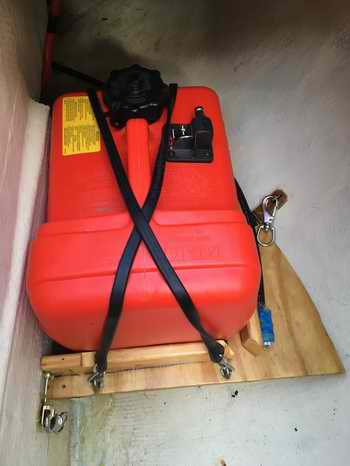
 COCKPIT
- A
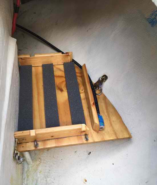
false floor in the port locker to support a fuel tank. Due to the
short fuel line that came with this tank Randy installed a false floor in
the end of the locker. One advantage is that it should prevent
things from sliding to "no man's land" back there. As it turns out
it's easier and quicker to just remove the snap shackles and lift the fuel
tank and false floor as a unit. COCKPIT
- A
false floor in the port locker to support a fuel tank. Due to the
short fuel line that came with this tank Randy installed a false floor in
the end of the locker. One advantage is that it should prevent
things from sliding to "no man's land" back there. As it turns out
it's easier and quicker to just remove the snap shackles and lift the fuel
tank and false floor as a unit.
|
|||||||||||
|
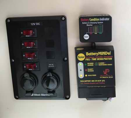
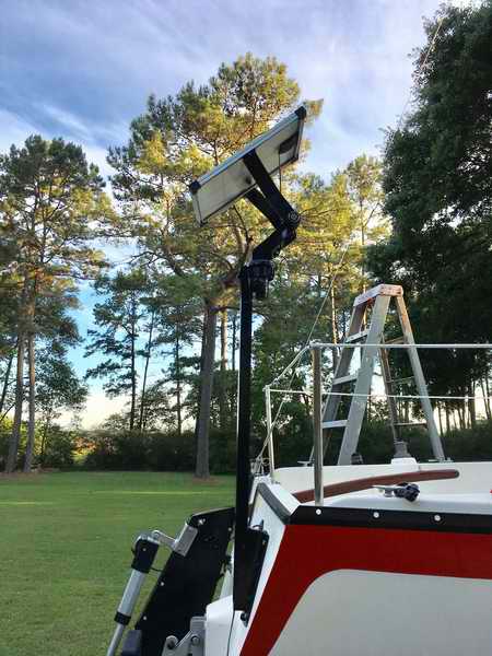
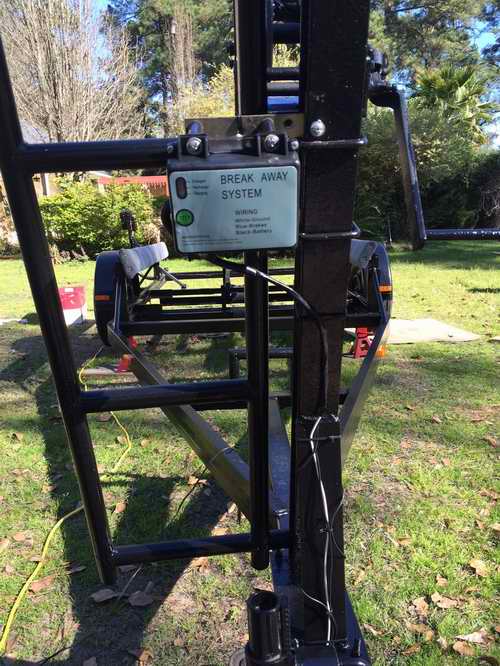
ELECTRICAL -
A new power panel, full articulating solar panel and solar charge controller
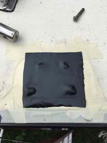
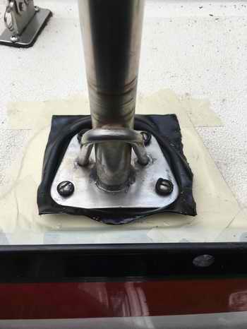
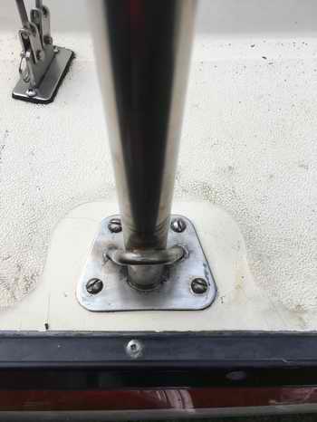
for the battery. This mounting post is sealed to the transom with
butyl rubber and through bolted to a backing plate on the inside of the
transom. That's a reach to get back there. definitely a 2 man job. The
post/panel will be out of the way for day to day boat
handling. By the way, the articulating arms are from a tri-pod
mounted telescope.
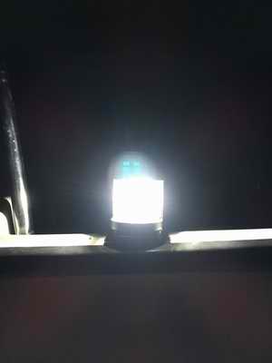
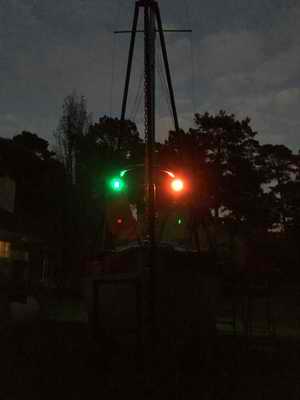
Then Randy converted all the running lights from incandescent to LED. |
|||||||||||
|
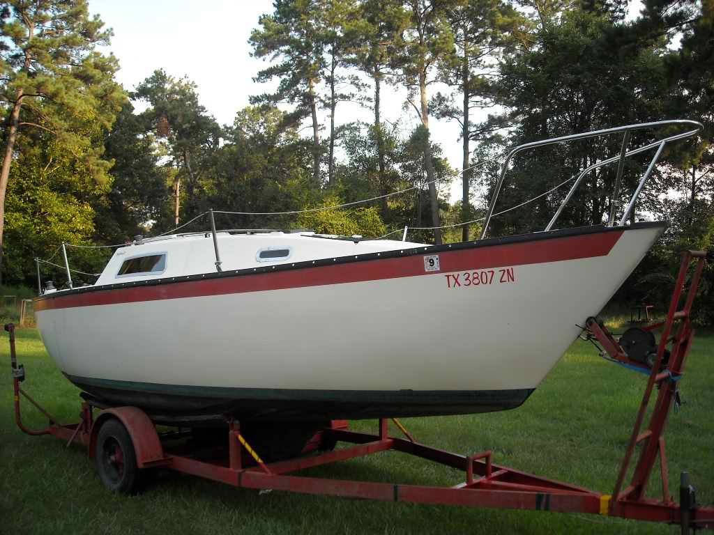
FURLER - Furling issues finally resolved with the Hood furler. When you
acquire a used unit it's sometimes difficult to determine how to assemble it
when pieces are scattered, or missing. Below the 150% genoa is
on with new sheets attached.
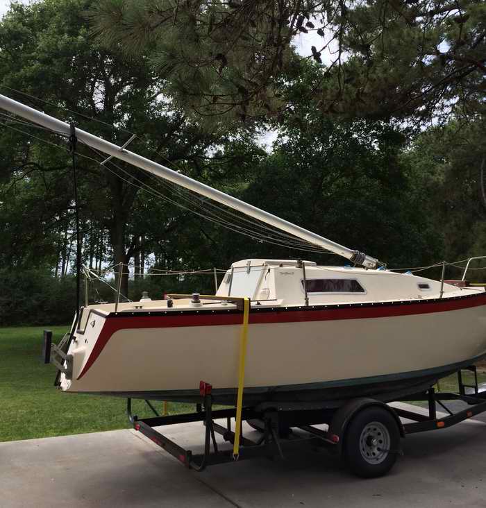
The frame work at the bow is Randy's mast raising hardware as he is
continuing to work on Emunah in the back yard. Launch is planned for
some time in 2018 or when he can get a break from work. |
|||||||||||
|
Return to Tech Tip Index.. . . . . . . . . . . . . . . Have a Question? |
|||||||||||
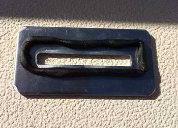
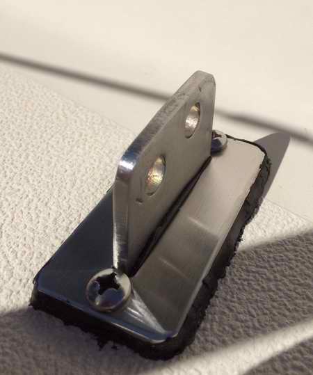
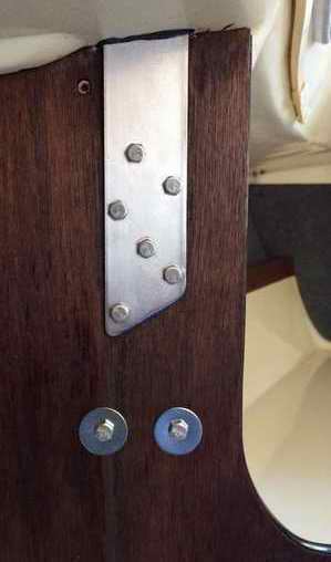
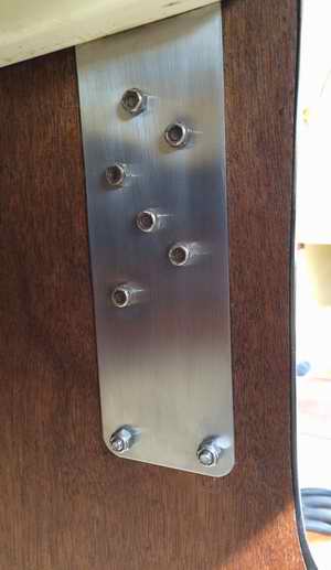 The
bulkheads received several coats of stain and varnish to spruce them up.
The chain plates were polished and sealed at deck level. You can see
a bit of butyl rubber sealant that oozed through the deck when Randy
heated the joint. You couldn't ask for a better seal. You are
looking at the aft and forward sides of the bulkhead. Instead of
installing washers behind the nuts, he installed a single
stainless steel plate to improve the overall integrity of the standing
rigging. In addition, he added two extra bolts
at the bottom for even more holding power.
The
bulkheads received several coats of stain and varnish to spruce them up.
The chain plates were polished and sealed at deck level. You can see
a bit of butyl rubber sealant that oozed through the deck when Randy
heated the joint. You couldn't ask for a better seal. You are
looking at the aft and forward sides of the bulkhead. Instead of
installing washers behind the nuts, he installed a single
stainless steel plate to improve the overall integrity of the standing
rigging. In addition, he added two extra bolts
at the bottom for even more holding power.
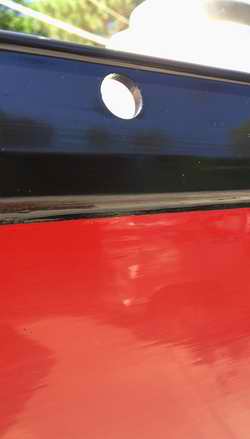
 It may
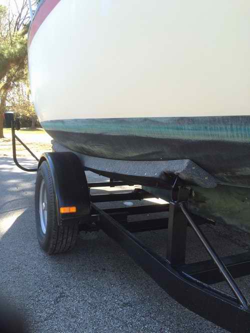
not be apparent in the photo above but the exterior of the boat received some much needed treatment.
It was badly oxidized and the cove stripe was worn where the fenders
rubbed
for way too long.
It may
not be apparent in the photo above but the exterior of the boat received some much needed treatment.
It was badly oxidized and the cove stripe was worn where the fenders
rubbed
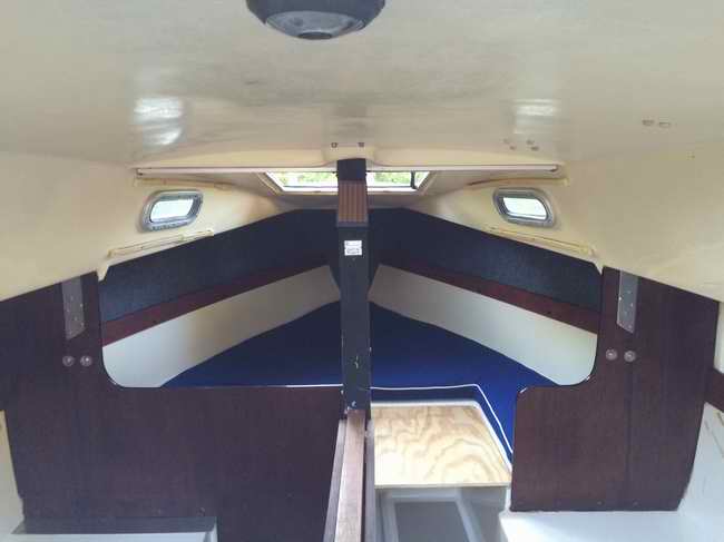
for way too long. 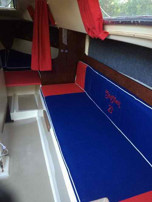 Randy
covered the settee cushions in a Texan theme and added a nice SJ23 logo in the seat
back. He is also making his way through the various "electrical nightmares," corroded connectors
and splices and replace defective switches. This time everything is being soldered and covered in
grease to prevent corrosion. Shown below is his cabin with LED
lighting.
There is even one under the table to create that floating effect.
This would be very effective to eliminate glare over dinner
conversation.
Randy
covered the settee cushions in a Texan theme and added a nice SJ23 logo in the seat
back. He is also making his way through the various "electrical nightmares," corroded connectors
and splices and replace defective switches. This time everything is being soldered and covered in
grease to prevent corrosion. Shown below is his cabin with LED
lighting.
There is even one under the table to create that floating effect.
This would be very effective to eliminate glare over dinner
conversation. 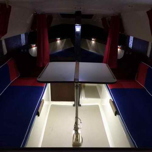
 With
this photo Randy is working on the mast stepping hardware and procedure.
He can now raise and lower the mast with ease on his own. It has to work easy since he will likely trailer launching her solo
for his trips into the Gulf of Mexico.
With
this photo Randy is working on the mast stepping hardware and procedure.
He can now raise and lower the mast with ease on his own. It has to work easy since he will likely trailer launching her solo
for his trips into the Gulf of Mexico. 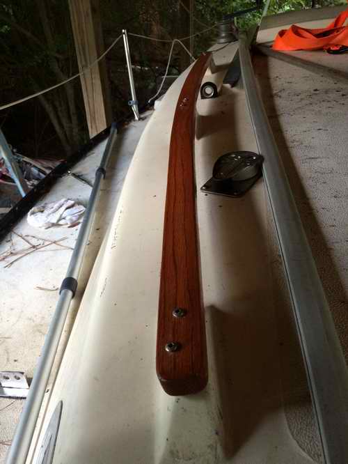 Time
for new hand rails on the cabin roof. Only one rail was intact to
pattern from. The other was good for firewood. Randy decided to
cut two new rails from solid red oak. They are about 1/4" oversize to
add strength and improve grip. For his procedure read
Time
for new hand rails on the cabin roof. Only one rail was intact to
pattern from. The other was good for firewood. Randy decided to
cut two new rails from solid red oak. They are about 1/4" oversize to
add strength and improve grip. For his procedure read