HAIL PROTECTION: Our lake
gets some very nasty thunder storms with golf ball size hail in early
to mid summer and I didn't relish the prospect of loosing another
panel to those icy demons.
I held off
installing hail protection for many years, thinking that panel overheating or filtering sunlight would
reduce
the charging performance. Heat is one of the greatest killers of electronics which is the major reason why I did not install a hail cover over the panels for so many years.
It
was time to confirm this idea.
As the temperature of a panel increases the output power is reduced at ~.258 %/0C. Panel output is rated at 250C (770F) which will drop
to ~20% at 300C (900F). For this reason there
should be an air gap behind the panel to cool it or install it against a cooling heat sink. If the panel is
installed at a slope it self cooling in the sun to reach optimal output. This also makes it self cleaning in the rain and prevents standing water from creeping into the edge of a rigid panel.
My experiment proved that a Lexan cover does not reduce
the light and there was only a slight temperature increase.
So.....
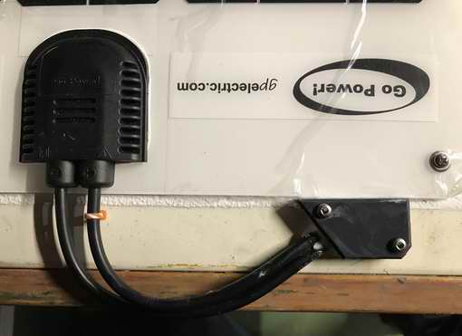
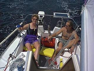
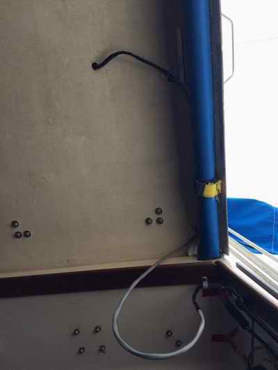
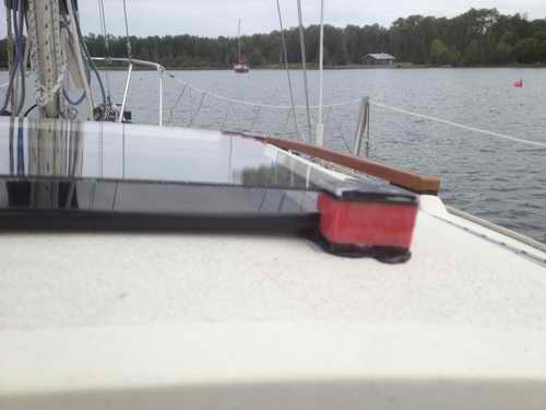
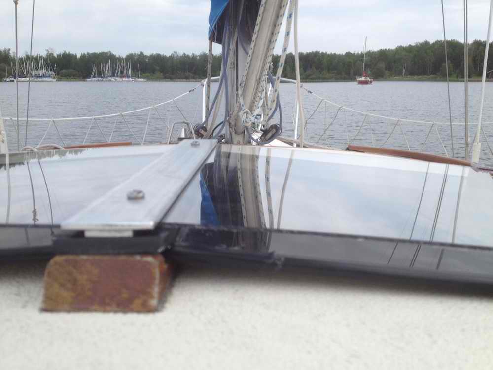
There are times when more power is needed to do major surgery on a boat. I was in that situation when Panache was secured in a new slip that was conveniently close to my truck for tools and parts. I was not going to pass this up. The previous owner installed a thru-hole in the aft end of the cockpit foot well. It wasn't being used so I extended a third charge cable through it with enough slack to position a panel anywhere in the cockpit. I learned a lot about solar charging by living onboard that week. When not needed, I simply pushed the cable back in the hole where the excess lay loose under the cockpit. The hole was then sealed with a bit of neoprene rubber.
TEMPORARY RIGID SOLAR PANEL
(Panache
version 6, 2024)
|
|
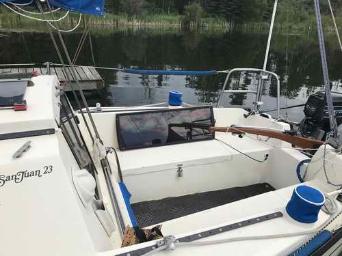 My project was going to take a week and some extra power would be useful. So I borrowed this 30W panel and converted the connector to complement the one on the third power cord you see coming out of the cockpit foot well. When that cord is not used I push it back to the thru hull and jam it in place with some foam. Hey it works. The panel can be secured to the winch with a light line (not shown). My project was going to take a week and some extra power would be useful. So I borrowed this 30W panel and converted the connector to complement the one on the third power cord you see coming out of the cockpit foot well. When that cord is not used I push it back to the thru hull and jam it in place with some foam. Hey it works. The panel can be secured to the winch with a light line (not shown).
When not needed, the panel fits (24x24)" at the back of the
starboard locker (Tech Tip B19) behind the life jackets and fenders. That part was pure fluke. Not everything I do is engineered to work!
In future I may mount this panel on the pushpit to pick up 3 hours of morning sun. This would be beneficial during the shoulder seasons when the sun is low in the sky. It has a metal backing that will make it easy to attach a bracket to.
The third input
cable coming out of the foot well is wired in parallel with the two panels on the sliding hatch. The output of all solar panels is controlled by BKR
12 from where the combined flow of electrons continue their merry ole journey to
the charge controller, ready for the next demand of juice.
|
|
Oh Oh - On my first day of my renovation work in 2021 I
used a
day's worth of power on a cloudy day. This was the first day of a week of cloudy weather. I
was surprised that the 2 rigid solar panels on the sliding hatch could not restore the battery in this low light. "Amazing what you discover when you
use the boat daily compared to weekend only." This low
charge rate is not
viable for
daily cruising when
the
solar array must maintain the battery charge and/or restore it to full capacity by evening. It's
bad for a battery not to be topped up promptly. I borrowed this 30W panel for the remainder of the week
and the charge controller restored the Optima AGM battery
the next day. Armed with this
knowledge I decided to upgrade Panache's solar array
and charge controller for 2021. Like I said, "Its amazing what you learn when you spend time onboard." TOP
|
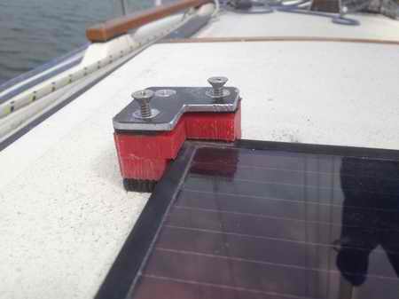
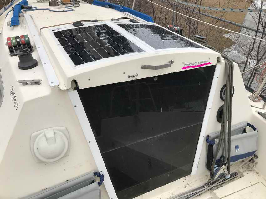
FLEXIBLE SOLAR PANELS (Panache
version 6, 2021) - When I was working on Panache in her new slip the moving shadows and cloudy weather limited the solar performance over the course of a day. This is the primary reason why I installed two 35W flexible shade tolerant panels, replacing the two rigid 5W thin film panels. The dimensions of the
none-slip area on the sliding hatch is (31x25)" which
is perfect to install a couple of (15x24.5)" panels, covering
~90% of the hatch. So during the winter of 2021 I installed two Go Power! Flex-35 monocrystalline flexible panels equipped with bypass diodes
(phew) to maximize efficiency. It was impractical to make the
panels removable for stepping the mast so instead I
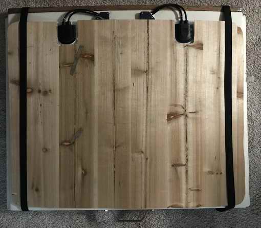
fashioned a sheet of 1/8" thick plywood to cover them. Its
the simpler solution and cheap
insurance. I hate when things get thumped for a minor foot slip.
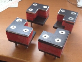
The first job was to restore the sliding hatch. I removed the feet installed in version 4. Its amazing how well the Sikaflex held those feet but a chisel and hammer won in the end. Some acetone and a wire brush on my Dremel Tool removed the stubborn
stuff deep down in the non-skid. A drill bit removed the Sikaflex inside
the screw holes. The holes were later filled with G/Flex epoxy to restore the water tightness. Lastly, I painted the hatch to
protect the epoxy and left it to cure for several days. All good as new.
FLEXIBLE SOLAR PANELS ON THE SLIDING HATCH
(Panache
version 6, 2021)
(Two Go Power! Flex-35 solar panels regulated by a
Genasun
GV-10-Pb-12V MPPT charge controller).
|
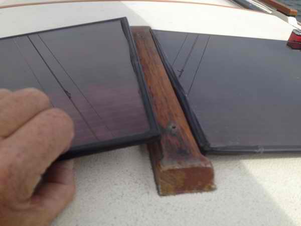
The flexible panels are oriented with the power cables
at the forward end of the SJ23 sliding hatch where they can go through the top with an easy,
low strain,
curve. I can't emphasize how important low strain will be over the years
with exposure to the sun as it minimizes the chance of insulation cracking. Orienting the power cables forward
keeps the end of the sliding hatch clear where I "tend" to lean
against it with the heel of the boat. It is a
comfortable place to stand with a nice motion in big waves. While Go Power! states this panel can be glued in place, I chose to fasten them with machine screws through the corner grommets so I can remove them if required. I drilled two additional
holes through the long sides of the panel to prevent them from fluttering in
a side breeze. Fluttering is a great way to quickly age a
flexible panel! These panels never move. The 1/2" thick hatch has a
balsa core that require the screw mounting and cable entry holes to be
sealed with epoxy. The holes were drilled oversize, filled with G/Flex epoxy, the hardened epoxy was drilled out to correct size, screws & cables passed through then sealed with Sikaflex. No leaks. See Tech
Tip G08 for older techniques.
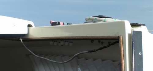
PS: Installing the cable through the sliding hatch required the removal of the MC4 connectors. The power wires were run under
the length of the hatch for cosmetics and weather protection of the terminal strip. They are wired in parallel at the terminal strip from where the power continues to the batteries via the boat harness. I previously tested the panels to confirm that steering diodes are not required. See note below about keeping a solar panel cool.
|
|
Fig 1 - Measuring the
hatch for two new flexible solar panels.
They will be a perfect fit!
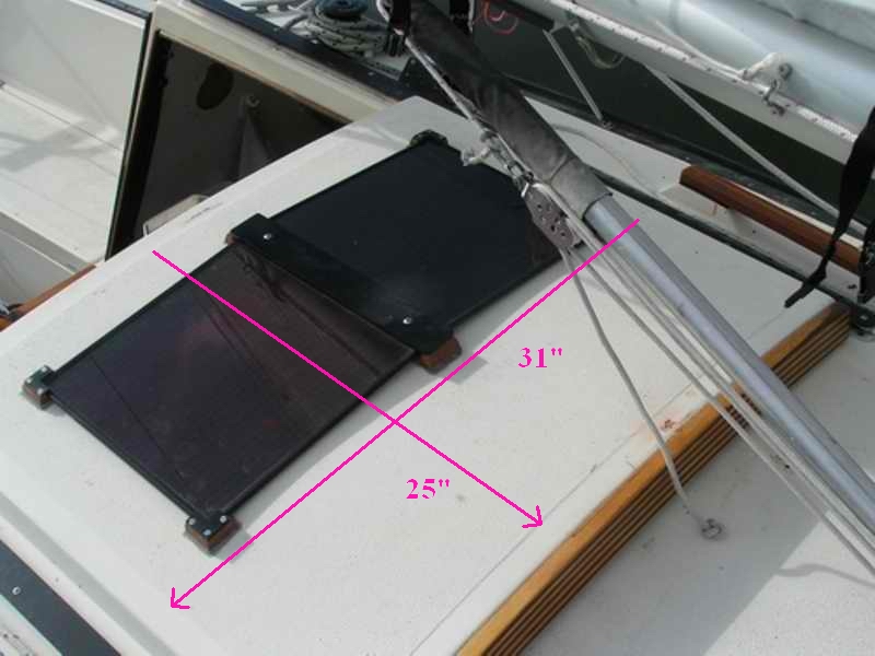 |
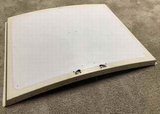
Fig 2 - The
rigid solar panels were removed and the screw holes filled with epoxy. The mounting
and cable entry holes for the new flexible panels were sealed with epoxy. Afterwards the surface was painted with 3
coats of acrylic.
 |
|
The two cable entry holes shown in Fig 2 were drilled at a
shallow 150 using a Pocket Hole Drill Guide clamped in position
to prevent movement of the drill bit.
The none-skid on
the hatch was painted white to protect the epoxy and to
match the colour of the solar panels. The underside of the
hatch was also painted white to brighten the cabin and make it
easier to clean. With cables in place (Fig 4) the holes were
sealed with silicon sealant and capped with a custom fabricated UHMW clam shell for
support and protection.
A final dry fit on Panache confirmed that
the bundle of wires and terminal strip can slide freely over the sill
through the full sliding distance of the hatch. Better to
be safe than sorry. On Panache the gap between the bottom of the hatch and the top of the sill
is 1 1/8" due to additional 1/8" thick UHMW glider under the
hatch rails. Without the glider the gap is about 3/4". See
Tech Tip B04.
|
|
Fig 3 - A dry fit for the #10 double jacketed wires. The natural, easy curve is just the thing for long life in the UV light of the sun.
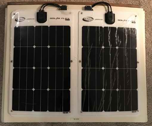 |
Fig 4 - The custom UHMW cap over the cable entry hole help to guide he wires and seal the hole. The #10 wire was formed to this curve to eliminate long term strain. The orange tagged cable is +.
 |
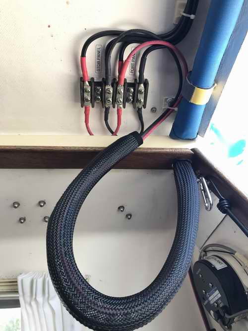
Panel to house wires are connected under the hatch with crimped and sealed lugs, ensuring a zero Ohm connection. Power lugs with dual holes in Fig 5 are used on the terminal strip so they don't loosen, ensuring a zero Ohm connection. The
vacant terminals are reserved to add 2 Schottky diodes, should they become necessary. This is also where the 28" loop of flexible wires
connect to the boat wiring harness on the starboard bulkhead. The
wire loop is covered in a woven nylon
sheath to organize the conductors as a unit. I also
replaced the previous smaller boat wiring harness with larger gauge (#10) wire to
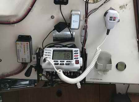
minimize loss, routing it further away from the VHF radio.
|
|
Fig 5 - The panel power leads are sealed at the entry holes and secured along the bottom of the hatch using existing holes. The flexible cable to the boat wiring harness is secured with a cable clamp next to the terminal strip. The cable bundle and terminal strip just clear over the sill at the front.
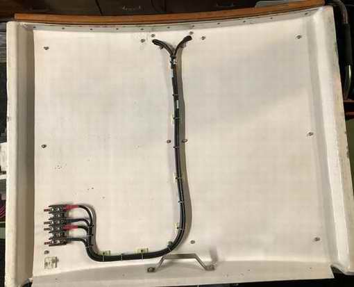 |
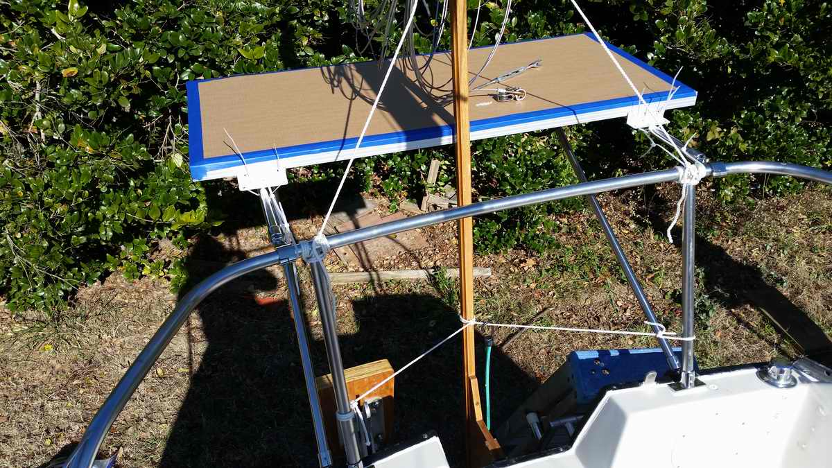
Fig 6 - Since the solar panels are
not removable, thin plywood may protect them when I work on
the deck. This is a prototype to test feasibility.
 |
|
INITIAL
PERFORMANCE TEST - On a sunny February day I pointed the Flex-35 solar panels to the sun and connected them to the AGM battery via a
Morningstar SunSaver MPPT charge controller. The sun was
at ~200 above the horizon with thin clouds scooting by. The panels charged the battery at 1-2 amps
during overcast
and slightly more than 3 amps during full sun.
Pretty good considering the low angle of the sun. Despite the low light, the battery reached
absorption mode after 2 hours on the first day and reached maintenance mode after
2 hours on the second day.
These solar panels do not require full sun. Their sunlight "acceptance angle" is quite wide and can generate power even on a cloudy day. The performance improvement going from 2x5 W to 2x35 W is impressive.
|
|
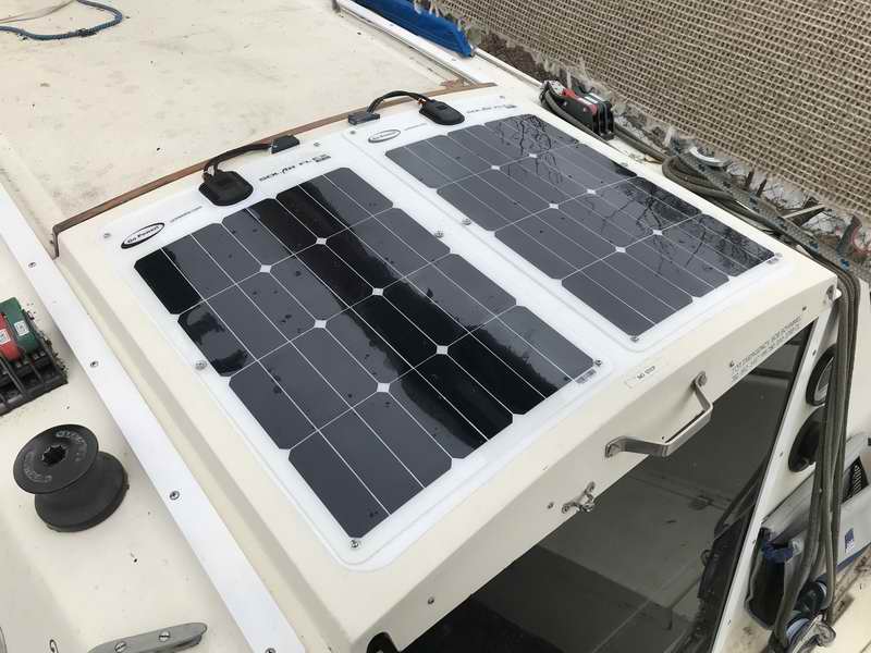
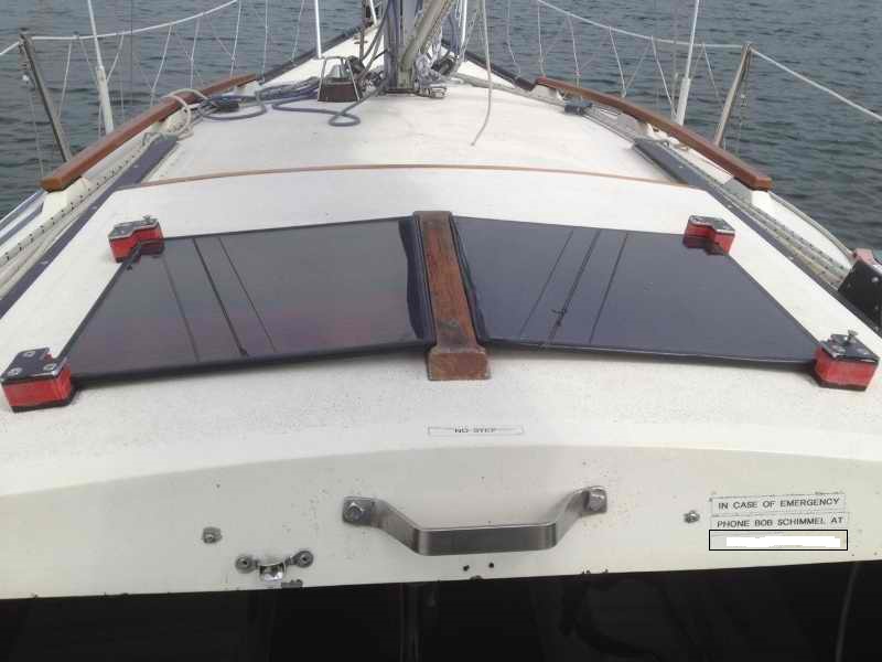
Fig 7 - Top view of solar panels
installed on Panache right after they were installed. Click here for a
different view. Notice that the hatch rails are now white so they stay cooler, minimizing thermal expansion.
|
|
Fig 8 - Flex cable "collapsed" with hatch closed. The 2 middle terminals pass equal power from the panels, operating the controller in bulk mode during a sunny day.
|
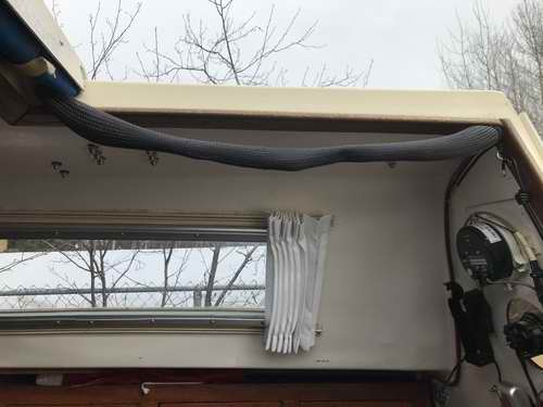
Fig 9 - Flex cable extended with hatch open. In
either case the flex cable is out of the way. It is now soft
with the sheath covering the wires and looks presentable.
HINT - To test the operation of each solar
panel darken one panel with a towel and view the
charge current and voltage of the exposed panel on the solar charge meter. Then cover
the other panel and repeat the measurement.
Since these
Go Power! Flex-35 panels are equipped with bypass diodes, pulling the towel back
slowly reveals the operation of each segment of the panel. PARTS -
Go Power! Flex-35 monocrystalline panel, Schottky diodes below.
|
|
REDUCE SOLAR PANEL TEMPERATURE WITH PASSIVE COOLING (2023)
- After a typical afternoon of full sun I measured the temperature of Panache's Go Power! GP-FLEX-35 watt solar panels. 55C is a tad warm to lean your arm on! While most panels have a maximum limit of ~80C, operating at this high temperature reduces the life and output power. At Panache's latitude (53.30N) and Alberta's intense sun light (due to clean, dry air East of the Rocky Mountains) I want long life with as much charging power as possible from these panels. So for these reasons I added a 3/16" thick sheet of Coroplast under the panels to create an air gap for passive cooling with the wind. The air passages are oriented fore/aft, in the direction of the prevailing wind through Panache's slip, light as it is.
A
week after the installation the panel temperature was measured at 48C on a similar sunny afternoon. I have not measured a higher temperature since, so Coroplast bodes well. Time will tell if this continues. So far they seem to produce slightly more power than mounted directly to the sliding hatch. You have to think creatively when using Coroplast to solve your problem. A blast of compressed air can clean the channels at the beginning of the season. Another possibility is a sheet of aluminum resting on spacers under the panels. Active Cooling - To
further cool the panels,
you could install
a 12V computer fans on the bottom of the hatch to blow air through the Coroplast or under the aluminum. The fans would have to be < 1/2" thick to pass through the 3/4" high gap over the sill, be powered directly from each panel, and be thermally switched to shut off when cool. This has the potential to cool a panel to ~30C. The bonus is they would improve ventilation through the cabin. This is a possibility I will leave for the future.
|
|
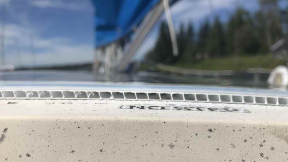
Coroplast under the Flexible Solar Panels - While Coroplast has impressive compression strength to support the panels, I wouldn't recommend stepping on them. Installing the Coroplast means NO STEPPING on the panels, which applies to sheet aluminum as well. This really isn't a problem as I've resigned to not stepping on the sliding hatch a long time ago. However, I'm impressed with how much weight it can support under my hand. Yes, it is easy to blow through the channels and you can see light through them as well. Unfortunately the camera can't show that. The mounting screws are tightened only just snug so as not to dimple the panel. This stress could delaminate a panel along with thermal expansion.
|
|
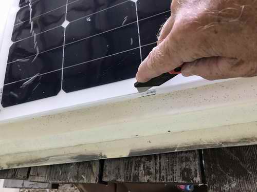
Trimming with a razor knife is amazingly easy.
 |
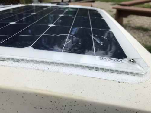
Cockpit view of trimmed edge.
 |
|
No Stepping on Panels.
 |
"Installing these solar panels demanded "perfection" since the skipper
has been known to steer Panache by the edge of the sliding hatch. Therefore, the panels were centered on the hatch, parallel with the center line of the boat. This is a tad difficult since the shape of the non-skid on the sliding hatch is a trapezoid. Didn't know that huh?. This
work was painstakingly slow; laying out hardware, measuring, determining pros &
cons, contemplating (tick tick, tick tick), reaching a final design, measure again, prep, paint, work a bit, epoxy,
wait, scrape a
bit, paint, repeat, etc. It turned out to be a perfect "time
consuming" project for the first COVID19 winter."
TOP
|
|
SECTION 2 - REGULATE
POWER
(Regulating power is about protecting the battery and appliances)
LINEAR REGULATOR (~1980s onward)
- A solar regulator must be used to prevent over charging a
battery,
especially a flooded battery where the electrolyte can be gassed off.
Prior to the 1990s
the
only choice was a linear regulator.
The silicon steering diodes D1 & D2 were required to
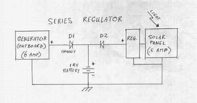 prevent discharging the battery at night and to steer the charging current to the battery during the day. Today the one way path for charge current is accomplished within the electronics of a solar charge controller. prevent discharging the battery at night and to steer the charging current to the battery during the day. Today the one way path for charge current is accomplished within the electronics of a solar charge controller.
Panache
originally had a shunt regulator and I seriously considered a series regulator, thinking it to be superior.
I
soon learned the difference is negligible. This argument can probably
be won by the same
person who can argue politics over religion!
There are three problems with a
linear regulator; it is barely functional with the
shade
& weather
variables
on a moving sail boat, it
applies very little charge voltage to the battery
 when the light is weak and the
external 1N4007 silicon steering diodes drop the voltage to the battery too
much. So I
abandoned my shunt regulator in favour of a
MorningStar SunGuard SG-4 PWM
charge controller. when the light is weak and the
external 1N4007 silicon steering diodes drop the voltage to the battery too
much. So I
abandoned my shunt regulator in favour of a
MorningStar SunGuard SG-4 PWM
charge controller.
A
solar "charge controller" is the marketing term used today for what was
initially called a "smart" regulator. The electronics is significantly
improved over the original linear regulators to maintain some charge
current during the low
light of dusk, dawn or shadow.
Some charge controllers have a low voltage disconnect (LVD)
feature to cut off the load when the
battery voltage is critically low, protecting the battery from permanent discharge damage.
Given
equal operating environments, a solar charge controller easily out performs a linear regulator.
 SOLAR PANELS
WIRED IN PARALLEL WITH STEERING DIODE - The
standing rigging on a sailboat has a habit of
blocking sunlight to a solar panel as the boat heels one way and then
another. The hull also turns relative to the sun, thereby casting a moving
shadow over the panels. For these reasons I
installed a solar panel on either side of Panache's sliding hatch, so at least one panel is
illuminated, most of the time. They are wired in parallel for maximum charge to the battery
and match the open circuit voltage to the controller. SOLAR PANELS
WIRED IN PARALLEL WITH STEERING DIODE - The
standing rigging on a sailboat has a habit of
blocking sunlight to a solar panel as the boat heels one way and then
another. The hull also turns relative to the sun, thereby casting a moving
shadow over the panels. For these reasons I
installed a solar panel on either side of Panache's sliding hatch, so at least one panel is
illuminated, most of the time. They are wired in parallel for maximum charge to the battery
and match the open circuit voltage to the controller.
NOTE - For equal performance, the solar panels and steering diodes must match each other. One of Panache's panels produced less
power than the other due to a steering diode I forgot to
remove from the external wiring harness. Removing it increased the panel
output .6V, resulting in a slightly more charge to the battery. The battery
voltage rose
from 13.1V to a healthier 13.9V with the panels producing equal power.
-
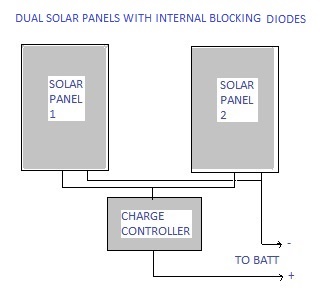
Panel with Steering Diode - If your panels are equipped with an internal steering diode (after ~1990s) then you can connect them in parallel sending the combined output to the charge controller input. All the power will go to the battery. DO NOT
exceed the input power rating of a PWM controller. It is OK to
exceed the input power of an MPPT controller provided you don't exceed
Voc. This was Panache's configuration with the two rigid panels on the sliding hatch.
(How to Test a Solar Panel for an Internal Steering Diode - Other than reading the panel documentation or physically seeing the diode, you can use a variable DC power supply e/w current limiting to
test your solar panel for the presence of an internal diode. Darken the panel so the output voltage is
0V as measured
with a voltmeter.
Then connect the power supply to the solar panel wires,
(+ to + and - to -) with current limiting set to
~100 MA. Slowly turn up the
power supply voltage to 15V while monitoring the
current. If no current flows (only uamps = no current) a diode is
present. If current flows, the panel needs an external Schottky diode
wired in series to block current from the other panel. Never having measured this current I think it would be in the low milliamp range.
-
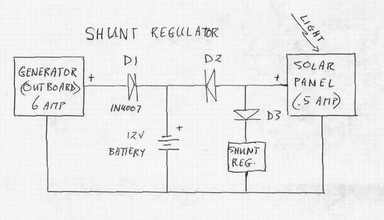
 Panel Without
Steering Diode - If your old (~before 1990s)
panels are NOT equipped with an internal steering diode then you
must add an external Schottky diode in series with
each to prevent the
shaded panel (lower output voltage) from absorbing the power from the illuminated
panel (higher output voltage).
Wire the combined outputs to the charge
controller input as shown at right. All the power will go to
the battery. Panel Without
Steering Diode - If your old (~before 1990s)
panels are NOT equipped with an internal steering diode then you
must add an external Schottky diode in series with
each to prevent the
shaded panel (lower output voltage) from absorbing the power from the illuminated
panel (higher output voltage).
Wire the combined outputs to the charge
controller input as shown at right. All the power will go to
the battery.
D1&D2 - Select a
Schottky diode that
can handle about 50% more
current than the
panel can generate. It must also have a peak inverse voltage (PIV) of
>30V. Its best to mount it on a heat sink where it can dissipate heat. Connect the leads to a terminal strip for secure connection.
Connecting a diode in "mid-air" to a wire is just asking for trouble.
-
A Charge Controller for each Panel -
The best system performance (most expensive but with redundancy) is a separate charge
controller for each panel with the outputs connected in parallel. No steering diodes are required as each controller
performs that function. The
combined power will go to the battery.
Solar Panel(s) with Outboard Generator
- A slight variation on this configuration is an outboard motor generator connected in
parallel to a single or dual solar panels. The generator consists of a
magnet in the flywheel spinning by a stationery pickup coil. The coil has a
diode in series with it to produce positive pulses (a half wave rectifier) of power, generating
~(5-6)A current. Connecting the generator in parallel to the solar panel(s) is
not a problem since the generator diode also blocks current generated by the
solar panels.
The solar controller is the steering diode for the solar panel. No external diodes
are required and the combined power will go to the battery.
NOTE - There is another reason to install a steering diode in front of each panel. It can block a higher voltage power spike from damaging a panel. TOP
SOLAR CHARGE CONTROLLER (PWM or MPPT)
-
Very much superior to a linear regulator
are two types of
solar charge controllers; one type uses Pulse Width Modulation
(PWM) and the other uses Maximum Power Point Tracking (MPPT).
PWM
- During bulk charging a PWM charge controller applies all the solar panel voltage
directly to the battery. In
absorption and maintenance modes a PWM
charge controller is
essentially a DC
to DC converter that charges a large
capacitor which is then discharged into the battery in pulses. This is the mode when a PWM
controller has gain over a linear regulator, about 50% more efficient.
MPPT -
An MPPT charge controller is about 15-20% more efficient than a PWM controller, achieving this by continually measuring (tracking) the maximum power
point (E & I) of the solar panel to be applied to the battery. This is a clever technique to transfer the
most power, during all 3 charge charge modes listed below. Get to know them
intimately.
With either type of charge controller the output is adjusted automatically in
proportion to the solar panel illumination (shade, angle & temperature), the
temperature of the controller & battery, the resistance of the wiring and finally the battery voltage.
|
CHARGE MODES |
PWM CHARGE CONTROLLER
(good technology for sunny weather) |
MPPT CHARGE CONTROLLER
(performs better than PWM, even in cloudy weather) |
|
BULK |
This
mode charges the battery to ~(80-90)%.
The
output power of the controller is constant, passing whatever power the
panel produces. This is the mode in which PWM gains
nothing.
- During low morning and evening light it continues to charge extending the charge time, albeit slower.
|
This
mode charges the battery to ~(80-90)%.
The controller continually measures (tracking) the maximum
power point of the solar panel to create a current gain, charging the
battery to the limiting voltage of the controller set by the type of
battery. This is the mode in which MPPT gains over PWM.
|
|
ABSORPTION |
This mode charges the battery
to ~(90-98)%.
As
the battery voltage rises to the controller limiting voltage, the output changes to DC pulses.
If the charge controller is installed next to the battery the internal
temperature compensation can reduce the output to protect the battery.
|
This mode charges battery
to ~(90-98)%.
As
the battery voltage rises to the limiting voltage of the
controller, the output
is
proportionally
reduced. The output is also
limited by the temperature of the controller
and
battery. There is little current gain in this mode.
|
MAINTENANCE
or FLOAT |
When
the battery is at full charge ~(98-100)%, the controller output is
further reduced
to a
trickle by reducing the pulse width to
maintain battery charge.
|
When
the battery is at full charge
~(98-100)%, the controller output is further reduced
to a trickle to maintain battery charge.
|
| |
|
|
|
NOTES |
The PWM pulsing action during the absorption and maintenance modes
applied to a flooded battery minimize plate
sulphation and prevent the electrolyte from gassing off. This leads to long
battery life and health.
|
If an MPPT charge
controller is configured to charge a liquid filled battery most can
automatically perform a monthly equalize charge across all cells. Other battery types are also maintained for long life and health.
|
Beyond
this, the description of solar panels and
charge controllers gets very technical and is beyond the
scope of this Tech Tip. It helps if you understand Ohm's Law, I=E/R. For a more
detailed description of pulse width or power point track charging, go the Morningstar web site. Learning is a daily exercise that tickles the
brain!
 PWM
SOLAR CHARGE CONTROLLER (2004)
-
The
SunGuard
SG-4
PWM charge controller manufactured by Morningstar
has an electrical efficiency ~50% greater than a linear regulator. That's
like adding a second solar panel and it costs about $30 Can, (2004).
Good bye linear regulator. The output is pre-set to 14.1 VDC which is
optimized for a flooded, gel
or sealed/AGM battery. It is internally temperature compensated to
adjust the output voltage which is
OK if
it is installed next to the battery. These
features
make the
SG-4 ideal for a pocket cruiser like a SJ23. Given the
electrical performance, waterproof packaging and reasonable cost I
installed an
SG-4
controller in 2005 and have had zero issues with it. PWM
SOLAR CHARGE CONTROLLER (2004)
-
The
SunGuard
SG-4
PWM charge controller manufactured by Morningstar
has an electrical efficiency ~50% greater than a linear regulator. That's
like adding a second solar panel and it costs about $30 Can, (2004).
Good bye linear regulator. The output is pre-set to 14.1 VDC which is
optimized for a flooded, gel
or sealed/AGM battery. It is internally temperature compensated to
adjust the output voltage which is
OK if
it is installed next to the battery. These
features
make the
SG-4 ideal for a pocket cruiser like a SJ23. Given the
electrical performance, waterproof packaging and reasonable cost I
installed an
SG-4
controller in 2005 and have had zero issues with it.
PS: I
was considering upgrading to the SunSaver MPPT
controller until I removed the external
steering diodes shown in the diagrams above. Turns out they were
redundant since my rigid solar panels were equipped with an internal steering
diode. The battery voltage increased .6V which made me a happy camper.
The
SG-4
is equipped with an internal
Mosfet
that is far more efficient and doesn't reduce the charging voltage to the
battery.
-
SIZE - About the size of a 2" cube.
-
TEMPERATURE
COMPENSATION - Internal. For optimal charging locate the controller adjacent to the battery to
"sense" battery temperature.
Operating range -40C to
60C.
-
CHARGE RATING - 4.5A input from a 12V solar array. It can handle an array rated at 64W output to
charge a 12V battery.
DO NOT
exceed the input rating of
30 Voc.
-
EQUALIZE CHARGE -
Cannot equalize charge a battery.
-
BATTERY SELECTION - The
output voltage charge curve is a compromise setting for
flooded, gel or sealed/AGM battery
types.
-
EFFICIENCY - About
75-80%.
-
CONNECTION
- The controller has 4 wires; 2
for solar array input, 2 for battery output. Ground connection is
negative battery.
-
INVERTER - Connect an AC inverter input directly to the
battery. The surge current during start up is too high for a
charge controller.
-
Also check out the section on
Electrical "Noise" reduction.
PRIMARY BUSS BARS - When I acquired an AGM battery I thought it high time to clean up the hickety potch wiring to the battery under the settee. This is when I fabricated the primary buss bars for Panache. Its quite an improvement and a bit of overkill for such a small boat but the electricity doesn't know that! You can read more about this in Tech Tip E02. From left to right is quite an improvement. 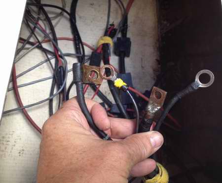 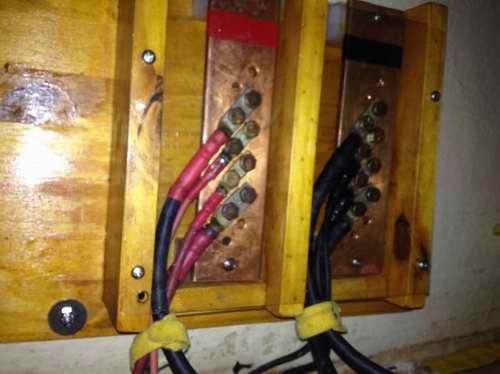 PANACHE
CHARGE WIRING with PWM CHARGE CONTROLLER (2016) - In the
diagram below (top view) the DC pulses
originating
from the SG-4 controller are fed directly to the battery via short, low impedance
wires. This is the desired wiring configuration for a single battery. The ferrite
beads completely
attenuate the DC pulses sent to the power panel wires, ensuring clean DC power for the VHF and AM/FM radios.
The
A PWM charge controller must be connected directly to the battery
and physically close to it so the impedance of the output wires does not
attenuate the high frequency charge pulses (PWM). It should also be installed
physically close
to the battery so it senses the same temperature as the battery.
Both of these ensure the highest possible
charge efficiency while protecting the battery.
NOTE -
So DO NOT connect the SG-4 controller at the power distribution panel. Doing so will apply the DC pulses to the boat's wiring harness and the "noise" will be heard on the VHF, AM/FM radio, or other sound system, making them almost unusable due to electrical noise. The "PWM noise" sounds similar to ignition noise from an outboard engine operating at a constant RPM. So, assuming your engine didn't radiate ignition
"noise" before you
installed the controller, a constant pulse rate after the installation is the telltale sign the interfering signal is coming from the controller via the wiring.
The solution is to install a ferrite RF noise suppressor bead over
each wire that feeds power into the boat's electrical system as shown
above. Most ferrite beads do an excellent job of attenuating PWM
& RF
interference signals on a wire. It is usually best to install a
ferrite bead close to the
signal source;
battery
or battery buss bar. In an extreme case you may have to install
several beads is series or
wrap the wire several times through the same bead. You can find an inexpensive source of ferrite
beads in the
cable bin at your local electronics recycle centre. That "bump"
on the end of a computer power cable is a ferrite bead. Cut
the cable off at either end of the bead and pull the cable out the hole. Voila
a useable ferrite bead. -
CONCLUSION
- If you consider the
variable light conditions on a moving sailboat,
a PWM solar charge controller is
an efficient device to charge a battery since it can still charge during low light, is dynamically regulated in proportion to sunlight, the electrolyte does not "boil" off and the
pulsing output removes any sulphate crystals from the plates of a
flooded battery. For
more detail info on pulse charging technology see Tech Tip E04.
MPPT SOLAR CHARGE CONTROLLER (2020)
- When
designing the charging system of an SJ23 the charge controller
should be considered first since it relates to system sizing and protects the costly battery
by charging it correctly. Problem is, an MPPT charge controller is a
pricey component for a small electrical system like on an SJ23. It's
one of the reasons why I stayed with a PWM charge controller for so many
years. Then in 2020 someone offered me a large solar panel that I just
couldn't refuse. Since the input current had the potential to exceed
the 4.5A limit of my PWM charge controller it was time for an upgrade.
So which charge controller to select?
|
COMPARE TWO EXCELLENT MPPT SOLAR
CHARGE CONTROLLERS
(Either of these charge controllers
is an excellent choice for an SJ23 as both are fast tracking and neither transmits RFI)
|
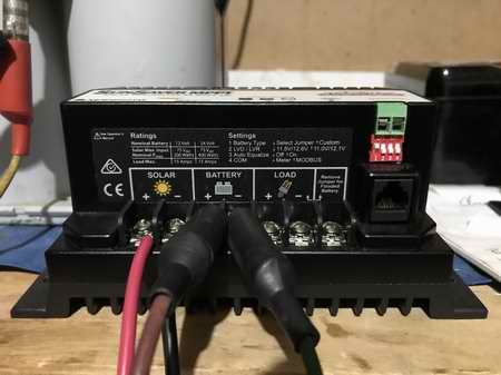
GENASUN
GV-10-Pb-12V -
This 10A MPPT charge controller does NOT transmit
RFI, is extremely fast tracking,
has
only 0.9MA
of self consumption current, and can recover a dead battery.
It was
installed on Panache in Spring 2021 and is
wired as per
diagram below.
-
Order from
GENASUN
Canada
10
year warranty.
|
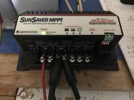
MORNINGSTAR
MPPT SunSaver
- This
15A MPPT charge controller does NOT transmit
RFI, is fast tracking
and has LVD.
The low voltage
disconnect is a feature that is just a tad important if you have electric start
with a single
battery.
- Order
from an authorized solar supply store. 5 year warranty.
|
SIZE - (5.5 x 2.5 x 1.2)".
|
SIZE - (6 x 2.5 x 1)".
|
RATING - 10A at 34Voc max (140W) input from a solar panel.
(It's OK to
oversize the solar array as the extra capacity can maintain the day time charge current
during marginal
light).
|
RATING - 15A at 75Voc max (200W) input from a solar panel.
(It's OK to oversize the solar array as the extra capacity can maintain
the day time charge current during marginal light).
|
EFFICIENCY - 96-98% electrical.
Charge current comes
on instantly with sun light.
(Fast MPPT tracking speed at 15
samples/sec while maintaining charge current).
|
EFFICIENCY - 94-99%
electrical. Charge current comes on instantly with sun light.
(Fast MPPT tracking speed while maintaining charge current).
|
OPERATING RANGE -
-40C to +85C.
|
OPERATING RANGE -
-40C to +60C.
|
ELECTRICAL CONNECTION - #10 wire; 2 from solar array, 2
to
common negative battery.
|
ELECTRICAL CONNECTION - #6 wire; 2 from solar array, 2
to
common negative battery, 2 to load, 1 for earth ground.
|
|
* CONNECTION
WARNING * - A solar charge controller
must always be connected to a battery (load). Switch the solar input off first to safely service the
system without damaging the controller. To facilitate this,
install a circuit breaker, fuse, or switch between the solar panel and the
charge controller input.
-
INSTALLATION - Connect the output (battery) first, then
connect the
input (solar panel).
-
SERVICING - Disconnect the input (solar panel) first, then the
output (battery).
-
MULTIPLE PANELS - Click here
if your
solar panels are connected in parallel.
-
TESTING - If the
solar panels are connected to a terminal strip, it creates a convenient
test point to measure and isolate a problem.
-
START UP CURRENT - Connect an
inductive load (inverter, motor, compressor or generator) directly to
the battery posts. The start up surge current of these devices is too high for a charge controller e/w terminals to connect a load or is equipped with a low voltage disconnect (LVD) feature. The start up current is also too high for a load shunt meter.
|
BATTERY SELECTION - A single jumper to select deep cycle battery charge rate
for
flooded or sealed/AGM. System charge voltage is fixed at 12V nominal.
|
BATTERY SELECTION
- Dip
switches to select battery type for
Gel,
Sealed, AGM or Flooded. System charge voltage is automatic, 12/24V.
|
EQUALIZE CHARGE -
Auto-equalize 1 per 28 days for a flooded battery. Disabled for other
battery types but check with manufacturer.
|
EQUALIZE CHARGE -
Auto-equalize 1 per 28 days for a flooded battery. Disabled for other
battery types but check with manufacturer.
|
BATTERY TEMPERATURE -
Internal sensor. For battery protection and optimal charging install the controller close to the battery to reduce the
charge current to a warm battery.
|
BATTERY TEMPERATURE -
External sensor.
For battery protection and optimal charging connect the temperature probe
to the top of the battery to automatically reduce the
charge current when warm.
|
INTERNAL PROTECTION - Over-charging, over-discharging, reverse polarity,
over-load, over-temperature and an internal 20A fuse. No LVD
to prevent battery discharge.
|
INTERNAL PROTECTION -
Over-charging, over-discharging, reverse polarity,
over-load, over-temperature.
LVD to prevent battery discharge if load connected to LVD terminals.
|
STATUS LED - Shows charging
mode (2 colour LED, very accurate). Best to post a laminated chart next to the controller to understand the following flash patterns.
-
Battery Charge Status.
2 sec green flashes = Ready to charge when solar available.
solid green = absorption or maintenance mode.
fast short green flashes = charging <3.7A (bulk mode).
slower, longer green flashes = charging >3.7A (bulk mode).
long, then short green
flashes = charging limit >10.5A (bulk mode).
NOTE - When the AGM battery is fully charged the Status LEDs alternate between fast short green flashes and solid green at about a 2 sec flash rate. Very convenient.
- Battery Alarm Status.
2 red flashes = high temp.
3 red flashes = current overload.
4 red flashes = battery V too low.
5 red flashes = battery V too
high.
6 red flashes = solar panel V too high.
2 long flashes followed by short
flashes = internal error.
|
STATUS LEDs -
Shows charging mode (dual LEDs, very accurate). Best to post a laminated chart next to the controller to understand the following flash patterns.
- Charging Status.
solid green = bulk mode.
1 sec flash = absorption mode.
2 sec
flash = maintenance mode.
red - error.
- Battery Status (SOC)
Full, Partial, Low. (Lit under matching battery image). -
Temp Sensor = high temp from remote sensor. Install the optional external Remote Meter
for precise measurements or use a PC to view 30 days of internal
logging. |
Radio Frequency Interference (RFI) -
The majority of MPPT charge controllers transmit radio frequency interference (RFI) to some
degree due to the internal DC switching. The sharp
power switching generates voltage transients that are transmitted as voltage spikes on the
boat wiring and radiated through the air (RFI), interfering with the boat's VHF and audio electronics through the antenna. I've tested the Genasun, SunSaver MPPT and
the Victron to know they are amongst the few controllers that don't transmit RFI.
Unfortunately my previous Renogy Rover Elite does, so for this reason it will be used elsewhere.
More on RFI
below.
|
|
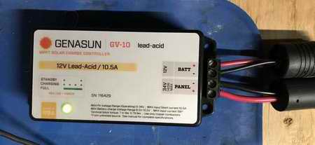
PANACHE
INSTALLATION - This
charge controller was installed
on the starboard bulkhead with the other electronics
as my
bench testing confirmed there is no RFI. If the
status LED shines green the controller is wired with the correct polarity. The flash pattern of the LED shows the charge rate, <3.7A or >3.7A, which is operational confirmation at a glance. For a
precise power measurement I read the meters on the power distribution panel. This Genasun GV-10 is working extremely well on Panache as is the Morningstar SunSaver on my friend's boat.
|
|
IMPORTANT for LONG TERM STORAGE
-
If the
battery is left onboard for long term storage and the solar panels cannot receive
sun to maintain the battery charge, then disconnect the charge leads
to the battery so the self consumption current of the MPPT charge controller does not discharge the
battery.
|
|
|
|
MPPT ISSUES SPECIFIC TO A SAILBOAT
|
|
RECOVERY FROM NIGHT TIME POWER DRAW -
Most MPPT charge controllers draw some power from the battery when the sun doesn't
shine. I was
curious to know how long it takes to recover the overnight deficit. For
this test I used a 2A variable power supply to simulate a
solar panel with the controller output power charging a 12V AGM battery.
Assuming 6 hours of darkness (no charge) below are my results.
|
GENASUN
GV-10-Pb-12V SELF CONSUMPTION - 1MA at 12V.
STARTS CHARGING - At ~2V above battery voltage with a smooth rise in charge current
that reaches maximum near instantly. (very fast tracking).
RECOVER NIGHT LOSS - Takes ~2 sec at 10A charge current.
|
MORNINGSTAR
MPPT SunSaver SELF CONSUMPTION - 25MA at 12V.
STARTS
CHARGING - ~2V above battery voltage with a smooth rise in charge current
that reaches max near instantly. (fast tracking).
RECOVER NIGHT LOSS - Takes ~50 sec at 10A charge current.
|
|
CONCLUSION - To recover the night time power loss first thing in the morning with either of these controllers takes less time than drinking a cup of coffee, which makes either unit an excellent choice! Be aware that the first morning light is weak and cannot produce full charge current till the input voltage is ~2V above battery voltage. Having said this, my Genasun charge controller is usually charging at about 5 AM in the summer. But then this is bluer sky Alberta. The lower quality charge controller manufacturers don't mention this parameter in their specifications. Hmmm.
|
TRACKING SPEED - There are two aspects to this:
- Q - How quickly can an MPPT controller start charging after the
resumption of solar panel output?
A
- While tracking speed is seldom
an issue for a permanent land based installation, movement and
shading are a constant issue on a sail boat. For this reason you
want an MPPT charge controller that can switch the charge power on immediately after the solar panel is illuminated and maintain charge while tracking.
- Q - How often does the controller sample the incoming power (samples
/ second) to
determine the optimal power transfer?
A
- The faster the better
and the controller should continue to charge while sampling. Some can't.
The fast tracking feature is very important on a sailboat. The following are all fast tracking charge
controllers suitable for a sailboat;
Genasun,
MorningStar,
Victron,
Midnite &
Outback.
Outback is designed for a solar array starting at 100W, so too big for
an SJ23. The most inexpensive controllers (not listed here) have slow tracking and
should not be considered for the dynamic conditions on a sailboat.
|
|
IMPORTANT for LONG TERM STORAGE -
If the
battery is left onboard for winter and the solar panels cannot receive
sun to maintain the battery charge, then disconnect the charge leads
to the battery so the self consumption current of the MPPT charge controller does not discharge the
battery.
|
PANACHE
WIRING with MPPT CHARGE CONTROLLER (2020) - In the
diagram below (looking at the top of the battery into settee) the DC power
originating
from the MPPT controller is fed directly to the battery via dedicated #10
stranded
wires. This is the desired wiring configuration for a single battery. While not required with a Genasun or Morningstar MPPT charge controller, I decided to retain the ferrite
beads to attenuate any RFI signal sent to the power panel wiring. If another
high load circuit is added to these buss bars, I will slip some ferrite
beads over those wires
as well. It
is the VHF radio and the media receiver that are affected by RFI on the power wires.
CONCLUSION
- The major advantage of an MPPT charge controller is
the power tracking feature that utilizes excess panel voltage to convert it
to useable charge current
during bulk charging.
Bulk charging occurs when the battery terminal voltage has not
yet risen to the limiting voltage of the controller.
This
is why an MPPT controller is about 15% more efficient
than a PWM controller. With this feature it can
typically
ram in 35% more power per day resulting in an average 90-95% state of
charge compared to 55-60% for a linear regulator. Just don't expect
the charge controller to maintain the battery from moon light, OK!
TOP
|
|
RADIO FREQUENCY INTERFERENCE (RFI) - All MPPT
charge controllers emit RFI to some degree due to the internal DC
switching used to regulate the output. The majority of RFI is
transmitted while the solar charge controller is charging the battery in bulk
mode.
Once the controller goes to maintenance mode (battery charged) the RFI is
usually much reduced, but can still be annoying. RFI on power cable can originate from the alternator, a cooling fan, a DC/DC inverter, certain LEDs, etc. RFI can also radiate through the
air or along power cables, acting as an "antenna". You can hear
the radiated interference when it breaks the squelch on your VHF radio, intermittent or continuous.
To understand the full scope of the interference listen to a quiet channel on the VHF, other than 16 or 9, with the squelch open. At times the quality of the NOISE can give you a hint as to the source of the unwanted signal. Tightening
the squelch is NOT a solution as this shortens the receive operating range. My tests
show the majority of the signal is radiated from the charge controller input wires
and
to a lesser degree the output wires. The RFI is broad spectrum
0-300 mHz, peaking around 150 mHz, as
shown on a spectrum analyzer. We also saw signal spikes
on the wiring that coincided with the switching frequency of the microprocessor
in the charge controller.
These are the noise bursts (squelch breaks) you hear on a VHF radio.
To ISOLATE RFI to a particular device, make use of the power switches:
- Confirm that VHF squelch operates correctly and set the volume to a comfortable level.
- Confirm if the radio is affected by the electrical NOISE. It may be intermittent. Another clue.
- If the NOISE is heard, open the squelch.
- Remove the antenna connector. If the NOISE is gone the signal is radiated through the air. If the noise stays on it is radiated on the power cables. Now you have to chase down the culprit so reconnect the antenna.
- Switch off the electrical power to all the devices on the boat, except the VHF. Shut off the MPPT charge controller by covering the solar panels or open the MPPT input wiring. Hopefully the NOISE is gone with one of these actions.
- Switch on each electrical circuit, one at a time, to determine which culprit is transmitting the NOISE. Be patient.
- NOISE could come from the alternator, a cooling fan, a DC/DC inverter, a solar charge controller, etc. DC electrical motors in general can be noisy. But then so can a loose power/ground connection or a high resistance connection.
- As a temporary solution you may have to operate the VHF with the culprit temporarily switched off.
- Follow the steps listed below to reduce or eliminate the RFI.
To REDUCE or ELIMINATE the RFI:
- Twist a pair of power wires
around each other, about 8 turns or more per foot, to correct the characteristic impedance to pure
resistance. Twisting adds inductance that cancels capacitance, leave resistance.
- Install the power wires away from
boat signal wiring. If the power wires have to cross boat wiring, do so at 900
for the least cross talk. This is always a good practice.
- Install the VHF co-axial cable
away from the power wires. This is always a good practice.
- The installation of
a ferrite bead over each power wire will attenuate the RFI, provided you
choose a bead that attenuates in the VHF range. It is best
to slip a bead over each conductor. The composition of a ferrite bead determines the
frequency band it attenuates; 30kHz-100mHz or 100-500mHz are
two examples.
I'm not sure what composition determines the impedance of a bead but highest
attenuation (dB) is
best. You will have to search through
an electronic wholesaler for these. If
one bead isn't effective try installing a second bead adjacent to the first.
Alternatively loop the wire several times through a large diameter
bead. A clamp on bead is easiest to install over an existing wire.
- Install clamp on ferrite on the VHF coax cable.
- Block RF In & Out - The optimum place to protect a device is
to install a ferrite where the power enters the device. The optimum place to
stop the signals from leaving a device (MPPT controller) is to install a
ferrite where the power leaves the controller. In the schematic above, the MPPT controller input
and output leads are both protected.
- While bench testing a
charge controller I
discovered the
addition of a power line RFI filter on the input and output leads
attenuated the RFI by 30dB. The interference (RFI) was reduced to only
2 feet as confirmed with a hand held VHF. Determining this
distance is tricky as my body was acting as an antenna. With my hand
close to the radio it broke squelch. However, these filters
typically limit the system current as well so this is a
questionable solution.
- Short Out RF - Install a .1 uFd ceramic disk capacitor across the input and output terminals
of the MPPT controller. The leads must be short to be
effective. The idea is to short out the RF signal back to its
source. This isn't the best technique but
it reduced the
signal propagation on Panache from 10M to only 2M distance, resulting in fewer
squelch breaks on the VHF.
- Short Out RF - Alternatively, install a .1 uFd ceramic disk capacitor from each
wire terminal of the MPPT controller to a thin copper plate installed
behind the controller using the MPPT mounting screws. This shorts out
the RF signal
to a low impedance ground.
To be successful the capacitor leads must be short, which I
couldn't do, so I can't confirm if this technique works. It would be more effective if the copper plate was
connected to earth ground, which we couldn't do.
- So far I tested the
Genasun,
MorningStar
&
Victron
MPPT charge controllers and confirmed them to be free of RFI. I'll add others to this list when I
can.
-
IGNITION NOISE - When an outboard engine equipped with an electric starter/generator
is operated, the generator and/or the ignition
may create electrical
"noise", imposing it on the boat
wiring harness. Steady ignition noise can make it near impossible to understand
speech on the VHF or listen to an AM/FM radio.
The operation of any other sensitive electronics may also be affected. You
can eliminate most of this with perfect electrical connections and ferrites on the charge power leads.
Never commit your installation design till all devices work in every mode. After that it is OK to secure the wiring.
ELECTRICAL "NOISE &
DAMAGING VOLTAGE SPIKES"
- The annoying hidden stuff.
-
STARTER - If
your battery voltage is low and you release the starter switch of
the outboard, the starter could induce a damaging voltage spike onto the
electrical wiring due to the sudden drop in current. Although I have not measured this.
-
INDUCTIVE LOAD -
Switching off an electric fan or other inductive load appliance can
induce a damaging voltage spike.
The spikes are opposite polarity to the normal
power and can therefore damage a delicate
LED, a
VHF radio, Tiller Pilot, or other
electronic device that is switched on and not protected from this.
Unfortunately most marine electronics is NOT protected against a voltage spike.
The fix
for this problem is to install a Schottky diode across the power leads of the
transmitting electrical device.
A Schottky diode can conduct the induced voltage spike quicker than a
silicon power diode, resulting in excellent protection. But if you can't find a
Schottky diode then a 1A silicon diode is next best. Connect
the striped end of the diode to motor positive
and the other end to motor negative. Connect it
electrically as close to the motor as possible. Also connect a diode
ahead of every LED circuit in the boat. The normal power flow to
or from the
motor is not affected.
NOTE -
A Schottky diode is a special type
of diode with a very low forward-voltage drop and very fast switching
speed, (faster than a silicon power diode). The
voltage drop of a
Schottky diode is between 0.15-0.45 VDC while the voltage drop of a
silicon diode is ~0.7 VDC. The lower voltage
drop is why it dissipate less power and the faster switching speed is why
it can short out the high
frequency "noise" spikes. This translates to better protection
and a quieter electrical system. See Tech
Tip E11. TOP
|
|
SECTION 3 - STORE POWER BATTERY - The boat battery
chemically "stores electricity" to supply DC power. It regulates the system voltage, discharges large current beyond what a solar panel or alternator can provide and absorbs electrical noise from the wiring. To
do any of these effectively the battery capacity must be capable of supplying sufficient power to operate the devices and the charging system should be sized to power the devices plus charge the battery as quickly as possible. The following are some golden rules concerning batteries.
-
A battery must be secured in place so it CANNOT
be dislodged when the boat lays on her side. It will happen!
-
For safety a flooded battery must be vented to the open to dissipate the hydrogen gas. Not so a sealed battery, AGM or gel.
-
For safety reasons a flooded battery must
have an absorption blanket under it capable of soaking up all the electrolyte.
While a blanket is not required for an AGM or gel battery,
the blanket spreads the weight evenly across the bottom and absorbs vibration to protect the plates.
-
A battery should be equipped with a cover or have covered posts to prevent an accidental short circuit across the terminals.
-
As a rule of thumb battery storage capacity should be double the daily consumption.
-
Charge and maintain each battery type correctly as per the manufacturer's recommendations.
A filled battery should be discharged to only 50%. The exception is the Optima spiral wound AGM battery that can occasionally be discharged to ~20% without damage. I have discharged Panache's Optima AGM to low without damage, but never fully discharged it to dead. A battery is an excellent absorber of transient voltages and a major component of an RF ground for the VHF radio. If you remove the boat battery during the off season, don't expect to have 12V available on the boat just because the solar panel is wired to the charge controller and exposed to sun light. A solar charge controller cannot generate 12V on its own; it must be connected to a battery. If you want workable 12V from the solar panel in winter, connect a small portable battery and draw power from it.
PHYSICAL SIZE - The battery must fit the SJ23 compartment, be accessible for inspection and removable for winter storage.
-
A Group 27 battery can fit under an SJ23 settee (L- 12.5", W-6.75", H-9.4") (L-32cm, W-19.5cm, H-23.6cm) and is likely popular for an SJ23.
-
A Group 31 battery can fit under an SJ23 settee (L- 13", W-6.75", H-9.5") (L-33cm, W-17cm, H-24cm) but is better placed under the cockpit due to its extra weight. BATTERY TERMINALS - The charge and discharge wires must be connected using ring lugs to the stud terminals.
They are the most secure and ensure optimal current flow. Battery terminals are manufactured in many styles and are generally coated for protection against corrosion. Terminals can be top or side mounted, with some batteries having both sets. Leave the unused terminals insulated for protection. A Group 27 battery generally has T6-7 6MM threaded or T-11 8MM threaded terminals. Observe correct torque specs to protect the thread and internal battery plates.
STORAGE CAPACITY - I can't imagine an SJ23 requiring more than 100AH of storage but then it all depends on how many "toys" you have on board and how long you want to operate them, either at anchor or for night sailing without charging.
BATTERY TYPE - The following battery types require the same type of lead-acid solar charge controller.
FLOODED BATTERY
- RV BATTERY - While there are many types of batteries, a popular one used on a pocket cruiser is a flooded deep cycle
RV battery. It can generate sufficient current to crank start an electric
start outboard, operate cabin lights and other "toys" on board. It can withstand long term charge/discharge cycles without damage but never full discharge.
The fluid level must be maintained up to the split rings in each cell. Look under the filler cap. A standard flooded battery is excellent for starting a diesel engine. If there are filler caps, the battery is NOT maintenance free, despite what is written on the label.
- GOLF CART BATTERY
- Two 6V golf cart batteries wired in series to create 12V will give excellent results on an SJ23. They have a very deep discharge cycle, meaning they can provide a steady stream of power for several days. They also have a high cycle life due to their thick plates. Most golf cart batteries are rated for 550 charge cycles to 50% depth of discharge. GEL BATTERY (VRLA) - A gel battery has
the advantage of having vibration resistance and extended life due to the thick putty like gel formed by adding silica dust to the electrolyte. No spillage but it is usually installed right side up for venting and a precaution to leakage. All are sealed and valve regulated. See Note 1. AGM BATTERY (VRLA) - An Optima Spiral D34/78 55AH battery has the advantage of having excellent vibration resistance and extended
life due to the fibreglass mesh that keeps the lead plates (99.99% pure lead) separated. The Absorbed Glass Mat (AGM) holds the electrolyte like a sponge to eliminate
spilling. All are valve regulated (See Note 1) and sealed so no spillage. But it is usually installed right side up as a precaution to leakage and for venting. I installed Panache's AGM right side up for both of these reasons. The battery can be operated from -40C to +65C (-40F to 149F) so safe to leave on boat during winter, albeit at reduced capacity. This is Panache's current battery and is by far the least expensive battery due to its long life, $/days and having finally died after 23 years of excellent service. See Note 2. LEAD CARBON BATTERY - A CANBAT Lead Carbon battery is designed to recharge must faster than an AGM battery, which is very useful on a moving sailboat with shadows dancing across its solar panels. With a designed float life of over 20 years at 200C, it offers more than 2,000 cycles down to 50% depth of discharge (DoD). It is constructed with premium sealed lead-acid chemistry with added carbon ingredients to the negative electrodes. The carbon ingredients increase power and minimize sulfation. This battery has pure lead plates and is sealed so no spillage. It is usually installed right side up as a precaution to leakage. It can be operated from -40C to +65C (-40F to 149F) so safe to leave on boat during winter, albeit at reduced capacity. The model CLC100-12 battery with 8MM terminals will fit nicely under the SJ23 settee.
NOTE 1 - Valve Regulated Lead Acid (VRLA) which means that a tiny valve keeps a slight positive internal pressure. NOTE 2 - I have installed numerous CANBAT CLC100-12 Lead Carbon batteries in various Alberta cell sites and none of them have failed during the last 15 years, performing exactly as stated on their web site. For this reason it is tempting to install one on Panache. However, in late 2023 I replaced Panache's battery with another Optima Spiral D34/78 55AH AGM battery for the following reasons: It is 30 lbs lighter than a Lead Carbon battery, the Optima stands up extremely well to vibration and rough handling, the battery tie down doesn't have to be changed, the Optima side posts result in no strain on the power cables, the Optima is a working configuration that doesn't require further research to function with the existing MPPT solar charge controller.
PROLONG LIFE OF AGM BATTERY - An AGM battery has a higher storage rating than a flooded battery. It is sealed so no gassing or filling cells with water. Equalize charging is not required but it is sensitive to overcharging. The voltage holds up better under a heavy load than does a flooded battery. Has low internal resistance so can be charged & discharged faster than a flooded battery. The spiral wound cell structure is extremely robust so less likely to deteriorate under vibration. The following tips help to prolong the life of your AGM house battery. Many of them apply to a flooded battery.
Battery Cycle - A battery cycle is one complete discharge and recharge; usually considered from 100% down to 20%, then back to 100%. Some manufacturers will rate their battery over a smaller depth of discharge; 10%, 20%, or 50%. Battery Life - Directly related to how deep the battery is discharged each time. If a battery is discharged to 50% each day it can last twice as along as a battery that is discharged to 80%. If a battery is discharged to 10% each day it can last five times as along as a battery that is discharged to 50%. However a battery that is continually discharged to only 5% or less will usually not last as long as one discharged to 10%. At very shallow cycles the lead dioxide tends to build up in clumps on the positive plates rather than an even film. An AGM battery is best suited for house use.
- While you can now buy an AGM designed for engine starting, a flooded battery is best suited for engine starting. Avoid discharging your AGM battery below 50% state of charge. Charge an AGM to at least 80-85 % state of charge on the first cycle and get to 100% state of charge as quick as possible.
- While an AGM can be left discharged at 50% for several weeks without damage, it is better to charge to 100% as quick as possible. Size your most powerful charging source for a minimum of 20% of bank capacity.
- This is usually an alternator or AC powered inverter/charger. For example, an Odyssey TPPL AGM battery prefers 40% of amp-hour capacity as minimum charge current. The best I can do on Panache is 5A (70W) of solar plus the 6A from the outboard generator. One of these days I will measure that because I doubt this much current can flow. Avoid installing the battery in an engine room or other hot area of the boat.
- Heat shortens battery life. Use temperature compensated charging for all charging sources.
- While an AGM battery can take a lot of current from an alternator, the heat created can shorten its life or cause premature failure. Therefore use a temperature controlled alternator with an external voltage regulator and temperature sensor that touches the top of the battery. Either of them can reduce charging accordingly to protect the battery. Use a smart solar charge controller.
- Not all solar chargers that claim to be smart are in fact smart. Some charge controllers start each day at a new absorption voltage charging cycle. This is not healthy for an AGM house battery that has low self-discharge and minimal parasitic loads. A smarter solar charge controller has a voltage trigger to drop it out of float charge mode. If it doesn't drop to the trigger voltage it remains in float mode. Using the correct charge & float voltage is a critical for an AGM battery.
- A charge controller that uses dip switches for programming often lacks the precise charge voltage for both absorption and float settings. Minimize the voltage drop in the system wiring for the best charging performance.
- With small gauge wire even a 3% voltage drop from 14.4V means just 13.96V at the battery terminals, thereby under charging the battery so it can never reach full charge. Low voltage robs the battery of the fastest charging potential, especially during a short duration, high current charge cycle. Know your correct state of charge at all times.
- This may mean investing in a battery monitoring device to help in overall cycle life. If you use voltage to determine state of charge be sure to measure it as accurate as possible, right at the terminals. Equalize charging is NOT recommended for an AGM battery.
- A flooded battery benefits from monthly equalize charging (higher-than-normal voltage to recover lost storage capacity).
Having said that, Lifeline Batteries states that careful equalization is possible with their AGM battery. But equalize charging must be configured correctly (and monitored closely) as the optimal process can vary by battery situation. Lifeline can help develop a custom equalization program for your boat batteries. At the completion of your installation, confirm operation by measuring and recording the voltage across exposed terminals.
- This is extremely important to understand the system for future maintenance and trouble resolution. Your memory ain't that good. ADVANTAGE OF AGM VERSUS FLOODED BATTERY
An AGM battery accepts charge current more readily than a flooded battery. An AGM battery converts as little as 4% of the electrical charge into heat, making them prefect for a solar panel. Whereas a flooded cell convert 15-20% of the electrical charge into heat. An AGM battery can dispense power at a higher rate than a flooded battery. A deep cycle flooded battery cannot deliver more than 25% of its rated capacity in amps without rapidly exhausting its charge. It is recommended to have a ratio of 4 to 1 between battery bank size and the largest load. Whereas an AGM is recommended to have a ratio of 3 to 1. This makes a significant difference when considering engine starting, etc. AGM self discharge is lower than a flooded battery. An AGM looses only 1-3%/month due to self discharge. Whereas a flooded battery can lose up to 1%/day. An AGM battery is not harmed by high current charging (or discharging) provided the charge voltage is correctly regulated (14.4V max) and the battery temperature is measured to prevent over warming. Any voltage higher than 14.4V will kill an AGM battery. An AGM battery operates safely in any orientation. They are sealed, so can't leak.
|
GENERIC CHARGING VOLTAGE for BATTERY |
| |
FLOODED |
GEL |
AGM |
| BATTERY AT REST |
~12.7 V |
~12.7 V |
~13.0 V |
| BULK CHARGE |
~14.2 V |
~14.0 V |
~14.4 V |
| ABSORPTION CHARGE |
~14.2 V |
~14.0 V |
~14.2 V |
|
MAINTENANCE CHARGE |
~13.7 V |
~13.7 V |
~13.7 V |
| EQUALIZE CHARGE |
~14.2 V |
Do NOT equalize |
14.5 V. See battery manual
if OK to equalize |
| BATTERY AT REST |
~12.7 V |
~12.7 V |
~13.0 V |
Recite the following if you can't remember voltage numbers for a battery at rest. 12.7 we're in heaven, 90% charged.
12.5 we're still alive, 70% charged.
12.2 there's a lot to do, 40% charged.
11.8 is just too late, dead.
DUAL BATTERIES CHARGED BY A SINGLE SOLAR CHARGE
CONTROLLER - An AGM battery should be discharged to only 50% of its capacity to keep it healthy. So if you want more capacity you should add a second battery. If wired in parallel they can be charged from the same controller. If wired separate the most efficient way to charge two batteries from
a single charge controller is to install a
Blue Sea
"ADD A BATTERY" switch. This electronic "A/B" switch is basically a voltage
sensitive switch that automates charging of two batteries from a single source without manual switching. If the ACR senses a charge is present on either battery it will offer the charge to both batteries. If the battery voltage drops to a preset threshold the ACR will isolate the batteries thereby maintaining the charge in the starting battery. Switching is achieved with "make before break" logic to maintain battery voltage to the output of the charge controller, thereby preventing controller failure. Its peace of mind to guarantee all your batteries are charged. The switch can be manually operated to deal with a power dilemma. I finally found the rules programmed into the ACR (Automatic Charge Relay). Its a very interesting device.
- RELAY CLOSED, HOUSE AND START BATTERIES CONNECTED IN PARALLEL
Battery = 13.6V for 30 seconds or 13.0V for 90 seconds. (Sensed at either the house or start battery).
- RELAY OPEN, HOUSE AND START BATTERIES SEPARATED
Battery = 12.75V for 30 seconds or 12.35V for 10 seconds (Sensed at either the house or start battery).
- Engine start isolation feature, momentarily opens the connection between battery banks while the starter motor is engaged.
- Over-Voltage Lockout at 16.0V – If the sensed voltage at either the house or start battery terminal is 16.0V or higher the ACR will lock out and open itself till the battery voltage drops to the correct value.
- Under-Voltage Lockout at 9.5V – If the sensed voltage at either the house or start battery terminal is 9.50V or lower the ACR will lock out and open itself to prevent further discharge.
BATTERY
DISCHARGE PROTECTION (LVD)
- Many larger sailboats have dual batteries.
One to crank the engine and the other to supply house needs. I think most SJ23s are
equipped with only one battery. If
you want sufficient power to start the outboard, operate the electronics or make that emergency
call on the VHF then you
must monitor the battery voltage. Digital VOMs are quite inexpensive these
days and I have seen them permanently mounted adjacent to the power
distribution panel. However this demands that you monitor it on a regular basis.
If
you can't monitor it and want to
preserve the battery charge then you require a
charge controller equipped with low voltage disconnect
(LVD) or a separate LVD to
remove the load
automatically. These devices are equipped with circuitry that monitors the battery voltage to automatically switch off
the electrical load at a preset low voltage. For specific products click on this Google search
result http://www.google.ca/search?hl=en&q=battery+discharge+protection&btnG=Search&meta=
HINT - Many MPPT charge controllers are equipped with a low voltage
disconnect (LVD) feature.
HINT - I go to great lengths to maintain Panache's battery charge by
minimizing the load and maximizing the
charge capacity. Most systems are designed
with this in mind and many diligent skippers likely do this, thinking it is the
optimal procedure. This practice is OK with a flooded, gell, or AGM or
battery when each cell is in excellent condition.
However the
problem with this practice is that if a flooded battery is never discharged then with time the
weakest cell will have the lowest voltage and the strongest cell will have
the highest voltage, the overall battery voltage remaining the same.
Then when the battery power is needed, it can't produce the rated current
and voltage for as long as it is rated. This situation is created by
never equalize charging a flooded battery to ensure all
cells are charged equally. If your charging system
is not equipped with automatic equalize charging you can achieve a similar effect by
cycling the battery occasionally (discharge to 50% then charge it). The
charger senses the low battery voltage and automatically charges it with a
voltage higher than float thereby equalizing the cells. If you
discharge by only 20% it should also achieve the desired results.
WINTER BATTERY MAINTENANCE
- Remove the battery from the boat and use an AC
powered
"smart charger" to
maintain the battery charge during the winter. Most of these smart chargers use 3 step bulk/absorption/float to maintain a battery
in a
healthy state. The optimal temperature to store the battery is just
above freezing. OK to sit on dry concrete. A flooded battery
should be charge equalized once a month.
I charged Panache's AGM battery once a month with a smart charger and use a Honda desulphate charger once a winter to clean the plates.
TOP
|
|
SECTION 4 - ON THE WATER OBSERVATIONS 2024 Observation - After four years of use I have experienced no problems with the Go Power! Flex-35 solar panels and the Genasun GV-10-Pb-12V MPPT solar charge controller. The two solar panels supply all the power I need through sunny or cloudy weather and the charge controller does not generate annoying RFI that affects or limits the use of the VHF or AM/FM radios. It's a working combination that I wouldn't change because I can now operate any device without fear of discharging the battery.
|
|
To use the stored electricity on your boat you need to distribute it safely.
So go to Tech Tip
E02. TOP
|
|
Return
to Tech Tip Index. . . . . . . . . . . . . . . Have
a Question? |
 ON
TOP OF THE SLIDING HATCH
ON
TOP OF THE SLIDING HATCH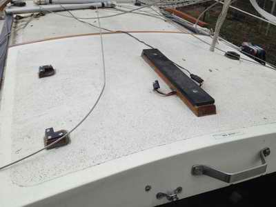